


3 - 1
SECTION 3 CIRCUIT DESCRIPTION
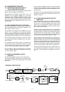
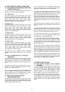
3-1 RECEIVER CIRCUITS
3-1-1 RF FILTER CIRCUIT (FILTER AND MAIN
UNITS)
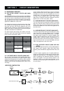
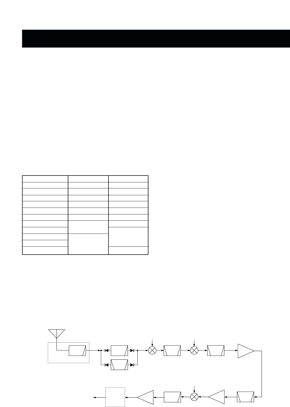
Received signals from the antenna connector are applied to
the transmit/receive switching and protection relay (FILTER
unit; RL7301) which is controlled by the CPU via the “TRXS”
line. The signals pass through the 30 MHz cut-off low-pass
filter (FILTER unit; L7321, C7321–C7323, C7325), and then
applied to the MAIN unit via the J7321.
The signals pass through the transmit/receive switch (D53)
and 1.6 MHz cut off high-pass filter (L51–L54, C54, C56,
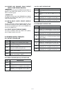
C57, C59, C61–C64), and are then applied to one of the
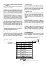
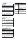
bandpass filters (including one low-pass filter for below 2.0
MHz). These filters are selected by the filter control signals
(B0–B8) as described in the table below.
The filtered signals pass through the 33 MHz cut-off low-
pass filter (L202, L203, C202–C206), and are then applied
to the 1st mixer circuit (Q201, Q202).
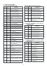
3-1-2 1ST MIXER AND IF CIRCUITS (MAIN UNIT)
The 1st mixer circuit converts the received signals into a
fixed frequency, 64.445 kHz 1st IF signal using PLL output
frequency. By changing the PLL frequency, only the desired
frequency is picked up at the pair of crystal filters (FI301a,
FI301b) via the 64.445 kHz bandpass filter (FI201) at the
next stage.
The IF amplifier (Q203) and resonator circuits are designed
between the filter pair. The PLL output signal (1LO) enters
the MAIN unit via the J601 and is amplified at the 1st LO
amplifier (Q601). The amplified signal is passed through the
100 MHz cut-off low-pass filter (L604, L605, C604,
C606–C610) to suppress harmonics components, and then
applied to the 1st mixer circuit (Q201, Q202).
3-1-3 2ND MIXER AND IF CIRCUITS (MAIN UNIT)
The 1st IF signal from the crystal filter (FI301b) is converted
again into a 455 kHz 2nd IF signal at the 2nd mixer circuit
(D302, L303, L304). The 2nd LO signal (2LO) from the PLL
unit enters the MAIN unit via the J301 to be applied to the
2nd mixer circuit.
3-1-4 3RD MIXER AND IF CIRCUITS (MAIN UNIT)
The 2nd IF signal passes through the low-pass filter (L305,
L306, C307–C311), and then applied to the IF amplifier
(Q401) via the ceramic bandpass filter (FI401). The ampli-
fied signal passes through the ceramic bandpass filter
(FI402), and then applied to the 3rd mixer circuit via the IF
amplifier (Q501). The 2nd IF signal is converted into a 12
kHz 3rd IF signal at the 3rd mixer circuit (IC501). The 3rd LO
signal (3LO) from the PLL unit enters the MAIN unit via the
J3601 to be applied to the 3rd mixer circuit.
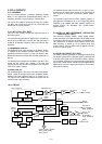
3-1-5 DSP RECEIVER CIRCUIT (MAIN AND DSP
UNITS)
The DSP (Digital Signal Processor) circuit enables digital IF
filter, digital noise reduction, digital PSN (Pulse Shift
Network), phase demodulation, digital automatic notich, and
etc.
The 3rd IF signal is applied to the IF amplifier (MAIN unit;
IC1002, pin 5) after being passed through the low-pass filter
(MAIN unit; IC1002, pins 3, 1). The amplified 12 kHz 3rd IF
signal is amplified at the differential amplifiers (IC651a/b),
and is then applied to the A/D convertor section in the
CODEC IC (IC501) on the DSP board (EX-2432). At the
same time, the converted signal is level-shifted 5 V to 3.3 V
in the IC (IC501).
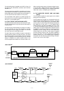
LPF
Antenna
FILTER unit
to transmit/receiver switch
LPF
FI301A
FI301B
FI401
FI402
Q401
Q5013rd mixer
IC501
IC1002
1st mixer
Q201
Q202
2nd mixer
Q201
Q202
1st LO
64—94 MHz
BPF
2—30 MHz
0.5—1.9999 MHz
BPF
Crystal
BPF
Crystal
IF
amp.
BPF
Crystal
LPF
IF
amp.
IF
amp.
DSP
UNIT
2nd LO
64 MHz
3rd LO
443 kHz
Frequency (MHz)
0.5–1.999
2–2.999
3–4.999
5–6.999
7–9.999
10–13.999
14–17.999
18–19.999
20–21.999
22–23.999
24–29.999
BPF ctrl signal
B0
B1
B2
B3
B4
B5
B6
B7
B8
LPF ctrl signal
L0
L1
L2
L3
L4
L5
L6
L7
• RECEIVER CONSTRUCTION