


3 - 3
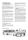
3-2 TRANSMITTER CIRCUITS
3-2-1 MICROPHONE AMPLIFIER CIRCUIT
(RC-25, MAIN AND DSP UNITS)
The microphone amplifier circuit amplifies microphone audio
signal to a level needed for the DSP circuit.
Audio signals from the [MIC] connector (J8701, pin 1) are
amplified at the AF amplifier (IC8280, pin 3), and then
applied to the gate modulator IC (MAIN unit; IC2001, pin 3)
via the J2051, pin 1 as “FMOD” signal. The signal is applied
to the DSP unit after being passed through the limitter ampli-
fier and low-pass filter IC (MAIN unit; IC1051, pins 3, 7) as
“DSPI1” signal.
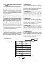
3-2-2 DSP TRANSMITTER CIRCUIT (DSP UNIT)
The DSP (Digital Signal Processor) circuit enables PSN
(Phase Shift Network)/Low Power/Phase modulator, trans-
mitter monitor, side tone, and etc.
The microphone audio signals from the MAIN unit via the
“DISPI1” line are amplified at the differential amplifiers
(IC651a/b), and are then applied to the A/D converter sec-
tion in the CODEC IC (IC501). at the same time, the con-
verted signals are level-shifted 5 V to 3.3 V in the IC (IC501).
The level shifted signals are applied to the DSP IC (IC301)
and modulated at the DSP IC to p[roduce the 12 kHz trans-
mitter IF signal.
The modulated IF signal from the DSP IC is applied to the
D/A convertor section in the CODEC IC (IC501) to convert
into the analog IF signal. Also the signal is level-shifted 3.3
V to 5 V at the level converter section in the IC (IC501).
The level-shifted IF signal is passed through the active filter
(IC701a), and then applied to the MAIN unit via J901 (pin
17) as the “DSPO1” signal.
3-2-3 SPEECH COMPRESSOR CIRCUIT
(DSP UNIT)
The DSP (Digital Signal Processor) circuit enables PSN
The speech compressor compresses the transmitter audio
input signals to increase the average output level (average
talk power).
When the speech compressor function is ON, the level-shift-
ed signal from the CODEC IC (IC501) is applied to the DSP
IC (IC301) and compressed at the DSP IC to obtain an aver-
age audio level.
At the same time, the compressed signals are modulated at
the DSP IC and applied to the D/A converter section in the
CODEC IC (IC501).
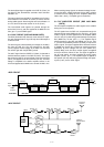
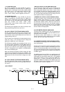
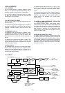
3-2-4 IF AMPLIFIER AND MIXER CIRCUITS
(MAIN UNIT)
The modulated 3rd IF signal from the DSP unit (“DSPO1”
signal: 12 kHz) passes through the transmit/receive swtich
(IC1703, pins 1, 5), and then applied to the 3rd mixer circuit
(IC901, pin 3). The applied 3rd IF signal is mixed with the
3rd LO signal from the DDS circuit (PLL unit; IC5701) to pro-
duce a 455 kHz 2nd IF signal.
The 2nd IF signal is output from IC901, pin 5 and passes
through the ceramic bandpass filter (FL402) to suppress the
unwanted signals via the D404. The filtered 2nd IF signal is
amplified at the 2nd IF amplifier (Q801), and then applied to
the 2nd mixer circuit after being passed through the D303
and low-pass filter (L304–L306, C304–C311, R306).
The 2nd IFsignal is mixed with 64 MHz 2nd LO signal, com-
ing from the PLL circuit, at the 2nd mixer circuit (D302) to
obtain 64.455 MHz 1st IF signal. The 1st IF signal is passed
through the crystal bandpass filter (FI301A, FI301B) to cut
off the unwanted signals. The signal is applied to the trans-
mitter mixer circuit (Q702, Q703) to obtain the desired sig-
nal via the transmit/receive switch (D301) and attenuator.
The operating (transmitting) frequency is produced at the 1st
IF mixer circuit (Q210, Q202) by mixing the 1st IF and 1st
LO signals. The mixed signal is then applied to the RF cir-
cuit.
FI402
Q801
MIC
BPF
Ceramic
LPF
6
IC1001
DSPI1 DSPO1
(12 kHz)
455 kHz
3rd LO
(443 kHz)
DSP
UNIT
IC1051IC2001
Controller
7
1
3
1
57
AMP. AMP.VCA
AMP.
2nd mixer
D302
2nd LO (64.00 MHz)
FI301b/a
64.455 kHz
Bandwidth:
15 kHz
Q401
BPF
Crystal
RF
amp.
1st mixer
Q702, Q703
1st LO
(64—94 MHz)
LPF
BPFs
2—30 MHz
0.5—1.9999 MHz
IC1
YGR
LPFs
PA UNIT FILTER UNIT
Antenna
D7271,
D7272
PWR
DET
Q6101, Q6801,
Q6851, Q6401,
Q6402
AMPs
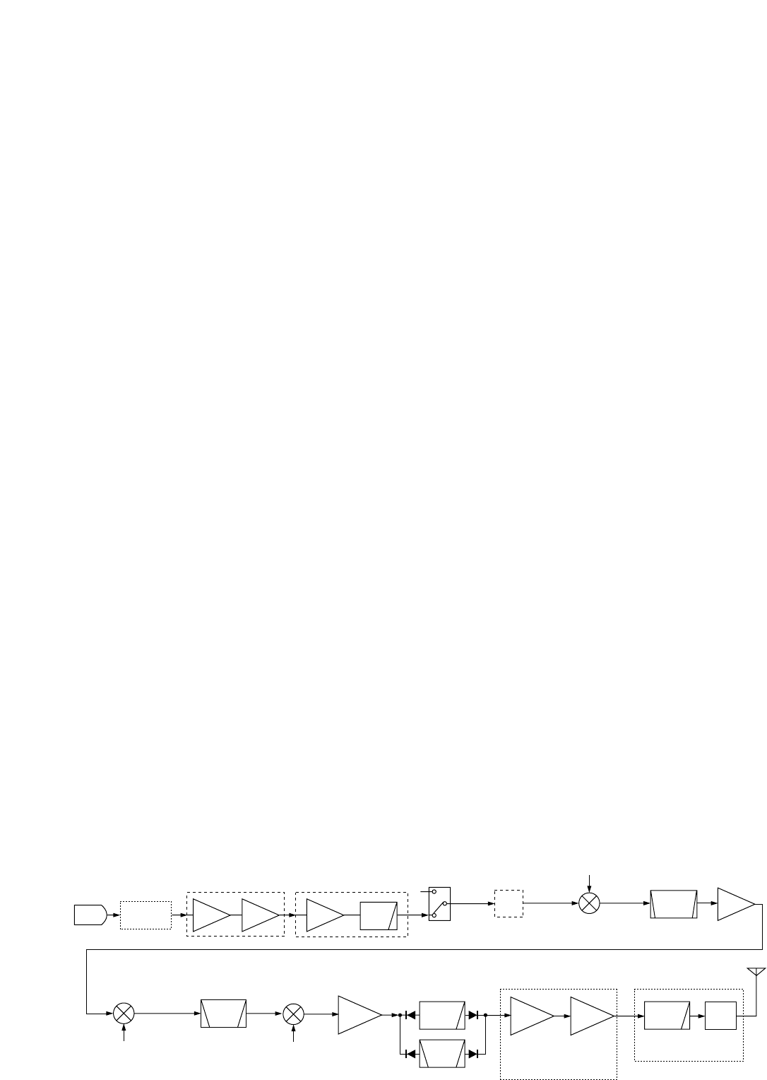
• TRANSMIT CONSTRUCTION