


3 - 5
• 14–19.9999 MHz signal
The signal is applied to the relay (FILTER unit; RL7211)
which is controlled by the band control IC (MAIN unit;
IC3602) as the “L16M” signal via the buffer amplifier (MAIN
unit; IC1301, pin 17). The signal passes through the low-
pass filter (FILTER unit; L7216–L7218, C7214, C7216,
C7217, C7221–C7225), and then applied to the RL7212.
• 20–29.9999 MHz signal
The signal is applied to the relay (FILTER unit; RL7241)
which is controlled by the band control IC (MAIN unit;
IC3602) as the “L22M” signal via the buffer amplifier (MAIN
unit; IC1301, pin 18). The signal passes through the low-
pass filter (FILTER unit; L7245, L7246, L7248,
C7242–C7244, C7247–C7249, C7253, C7254), and then
applied to the RL7242.
The filtered signal is applied to the antenna connector after
being passed through the RL7301 and J7311.
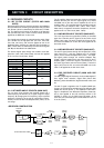
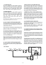
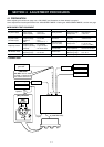
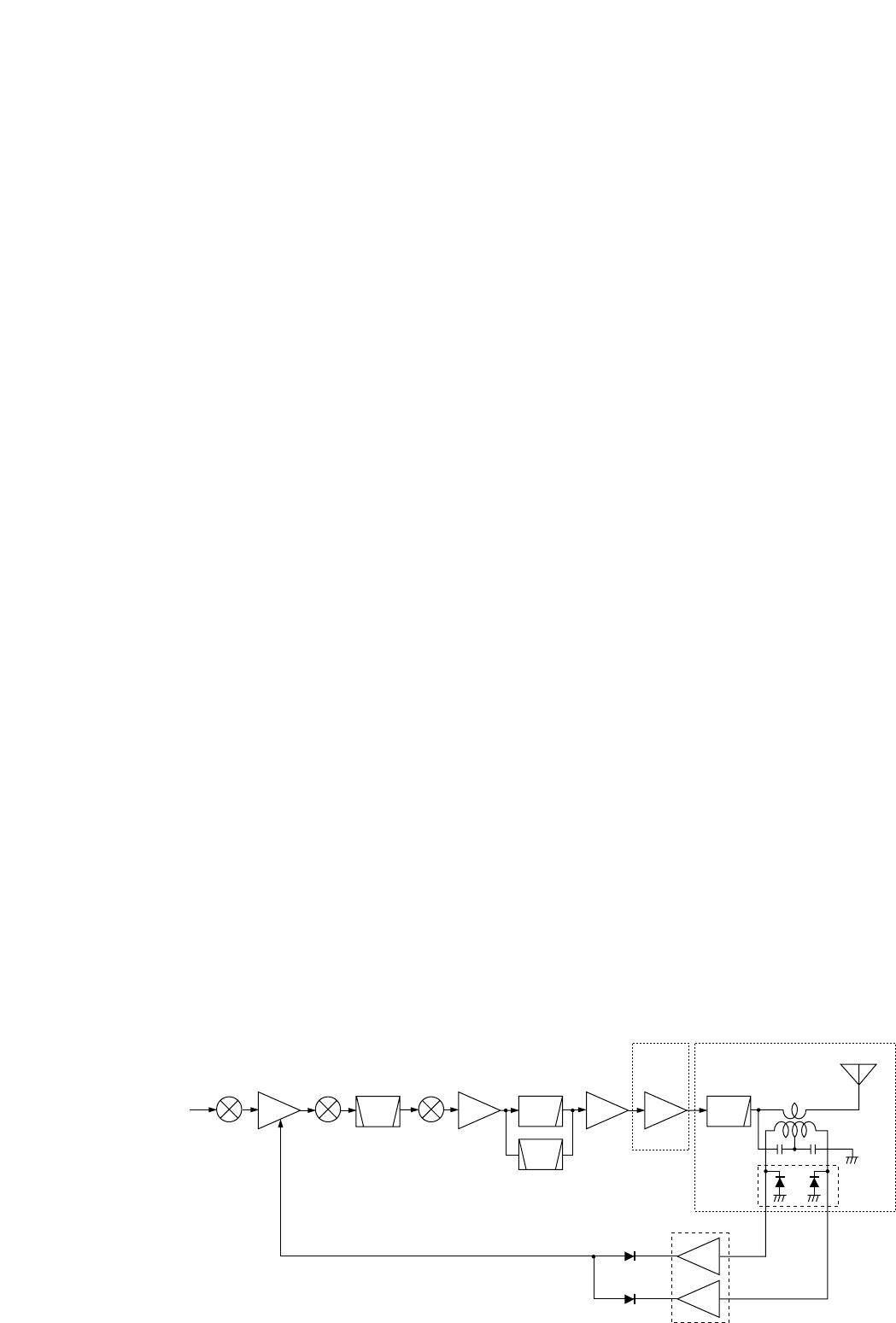
3-2-6 ALC CIRCUIT (FILTER AND MAIN UNITS)
The ALC (Automatic Level Control) circuit controls the gain
of IF amplifiers in order for the transceiver to output a con-
stant RF power set by the [RF PWR] control even when the
supplied voltage shifts, etc.
The RF power level is detected at the power detector circuit
(Filter unit; D7271) to be converted into DC voltage and
applied to the MAIN unit as the FOR signal.
The FOR signal is applied to the comparator (IC1201, pin 2).
The “POCV” signal, controlled by the [RF PWR] control via
the I/O expander (IC3606, pin 5), is also applied to the other
input (pin 3) for reference. The compared signal is output
from pin 1 and applied to the IF amplifier in the MAIN (Q801)
unit to control amplifying gain.
When the FOR signal exceeds the POCV voltage, ALC bias
voltage from the comparator controls the IF amplifiers. This
adjusts the output power to a specified level from the [RF
PWR] control until the FOR and POCV voltages are equal-
ized.
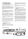
3-2-7 APC CIRCUIT (FILTER AND MAIN UNITS)
The APC (Automatic Power Control) circuit protects the
power amplifiers on the PA unit from high SWR and exces-
sive current.
• SWR APC CIRCUIT (FILTER AND MAIN UNITS)
The reflected wave signal appears and increases on the
antenna connector. When the antenna is mismatched,
D7272 of the power detector circuit (D7271, D7272, L7272)
in the FILTER unit detects the signal and applies it to the
ALC amplifier (IC1201, pin 9) in the MAIN unit as “REF” sig-
nal. The output signal decreases the bias voltage of the RF
APC amplifier to reduce the output power.
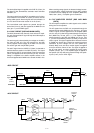
• CURRENT APC CIRCUIT (FILTER AND MAIN UNITS)
The power transistor current is detected from the different
voltage between both terminals of a 0.012 Ω resistor
(R6651) on the PA board. The detected voltage is applied to
the differential amplifier (IC6501). When the current of the
final transistors is more than 30 A, the detected voltage is
applied to the APC amplifier controller (IC1201) in the MAIN
unit to reduce the gate-2 voltage of the IF amplifier (Q801)
and thus reduce the output power.
3-2-8 RF METER CIRCUIT (MAIN UNIT)
The output of ALC amplifier (IC1201, pin 12) is applied to the
CPU (IC3303, pin 97) as “RFML” signal to indicate the trans-
mit power level on the display.
For antenna current meter indication, the “ANTM” signal
from the optional AT-130E is applied to the meter amplifier
(IC1201, pin 12) via the J6701 in the PA unit.
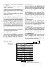
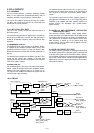
3-2-9 MONITOR CIRCUIT (DSP AND MAIN UNITS)
The micorphone audio signals can be monitored to check
voice characteristics.
A portion of the transmit IF signal from the DSP IC (IC301)
is mixed with a 12 kHz LO signal to demodulate into the AF
signals. The demodulated signals are level-shifted 3.3 V to
5 V at the level converter (IC102) to convert into the analog
AF signals. The AF signals are then applied to the MAIN unit
as “MONI” signal.
The “MONI” signal from the DSP unit is amplified at the AF
amplifier (MAIN unit; IC1603, pin 2), and then applied to the
VCA amplifier to control the AF volume (pin 7). The amplified
signal passes through to the AF mute circuit (MAIN unit;
IC1602, pins 1, 7) which is controlled by the CPU via the
expander IC (MAIN unit; IC3603) as the “AFMS” signal. The
AF signal is applied to the AF power amplifier circuit (MAIN
unit; IC1601, pin 1) to drive a speaker.
2
D7271
D7272
IC1201
9
1
8
LPF LPFs
BPFs
ALC
ALC amplifier
Antenna
FILTER UNITPA
UNIT
Power
detector
IF
ALC
Q801
TX
signals
Crystal
BPF
3rd mixer 2nd mixer 1st mixer
RF YGR PA
ALC
• ALC CIRCUIT