


3 - 2
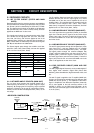
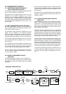
The level-shifted signal is applied to the DSP IC (IC301) for
the digital IF filter, demodulator, automatic notch and noise
reduction, etc.
The output signal from the DSP IC is applied to the D/A con-
verter section in the CODEC IC (IC501) to convert into the
analog audio signals. Also the signals are level-shifted 3.3 V
to 5 V at the level converter section in the IC (IC501).
The level-shifted audio signals are passed through the
active filter (IC701a), and then applied to the MAIN unit via
J901 (pin 17) as the DRAF signal.
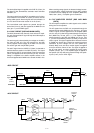
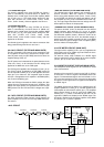
3-1-6 AGC CIRCUIT (DSP AND MAIN UNITS)
The AGC (Automatic Gain Control) circuit reduces IF ampli-
fier gain and attenuates IF signal to keep the audio output at
a constant level.
The receiver gain is determined by the voltage on the AGC1
line from the DSP unit. The D/A converter for the AGC
(IC102) supplies control voltage to the AGC1 line and sets
the receiver gain with the [RF/SQL] control.
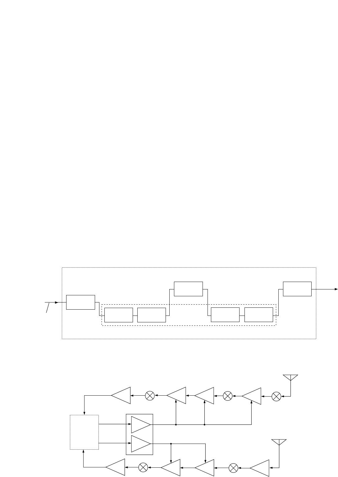
The 3rd IF signal from the CODEC IC (IC501) is detected at
the AGC detector section in the DSP IC (IC301). The output
signal from the DSP IC is level-shifted at the level converter
(IC101) and applied to the D/A converter (IC102). The AGC
voltage is amplified at the buffer amplifier section in the
IC102 and applied to the MAIN unit to control the AGC1 line.
When receiving strong signals, the detected voltage increas-
es and the AGC1 voltage decreases. As the AGC1 voltage
is used for the bias voltage of the IF amplifiers (MAIN unit;
Q203, Q401, Q501), IF amplifier gain is decreased.
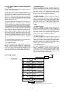
3-1-7 AF AMPLIFIER CIRCUIT (DSP AND MAIN
UNITS)
The AF amplifier amplifies the audio signals to the suitable
driving level for the speaker.
The AF signals from the DSP unit are passed through the
transmit/receive switch (MAIN unit; IC1703, pins 1, 6) via the
“DSPO1” signal, and then applied to the AF amplifier (MAIN
unit; IC1702, pin 5) after being passed through the low-pass
filter (MAIN unit; IC1702, pins 3, 1). The amplified signal
passes through the the SQL gate (MAIN unit; IC1701, pins
7, 1) which is controlled by the CPU (IC3303, pin 49) via the
“SQLC” signal. The signal is applied to the electronic volume
IC (MAIN unit; IC1603, pin 2) which can control the volume
attenuation by AFG voltage from the CPU (MAIN unit;
IC3303). Beep, tone, side tone, monitor signals are applied
to the the elecronic volume IC too. The signal is applied to
the AF mute swtich, and then amplified at the AF power
amplifier (IC1601, pin 1). The amplified signal is applied to
the speaker (SP-24) after being passed through the speak-
er jack (J1451) via the “AFO” signal.
DSP
UNIT
IC1101
AGC1
2
6
1
7
AGC2
AGC
AGC
IC1002
DSPI1
IF
amp.
IC2702
DSPI2
AMP.
Q2502
IF
amp.
Q2401
IF
amp.
Q2301
Q2302
RF
amp.
Q501
IF
amp.
Q401
IF
amp.
Q203
From the
antenna
IF
amp.
From the
DSC antenna
Differential
converter
IC651b/a
DSP UNITMAIN UNIT
CODEC IC (IC501)
IC301 IC701a
DSPO1
AF
signals
DSPI1
(12 kHz)
3rd IF
signal
A/D
converter
D/A
converter
Level
converter
Active
filter
Level
converter
DSP IC
• DSP CIRCUIT
• AGC CIRCUIT