


TH-K2AT/K2E/K2ET
11
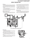
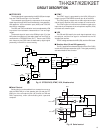
■ Voltage Detection Circuit
Various voltages are input to the A/D port of the MPU (IC8)
for processing.
Battery voltage is divided with resistors (R240, R241) and
enters the BATT terminal (pin 52) of the MPU.
Battery voltage is used for battery meter indication during
transmission or for alert tone processing when an abnormal
power supply voltage (approx. 16.5 V or higher) is applied.
Squelch voltage becomes DC voltage by detecting changes
in noise voltage in the FM IC (IC3), and the signal is used for
squelch control.
The S meter voltage is output from the RSSI pin of the FM
IC to control S meter display.
Detection of thermistor voltage (temperature) in the Ni-MH
battery during charging, detection of remote microphone key
pressing and VOX voltage monitoring are performed through
each A/D port of the MPU.
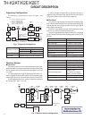
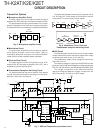
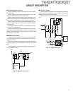
■ Battery Save Circuit
If there is no signal (squelch off, scan off or no key operation)
for longer than 10 seconds, the transceiver will enter the
battery save mode.
Battery save operation is performed by controlling Q57 with
an output signal from the 5C (SAVE) terminal (pin 15) of the
MPU.
The 5C ON/OFF cycle ratio during battery saving can be set
from a transceiver menu.
5MS
5C
5M
Q41
Q57
37
15
5MS
5C (SAVE)
IC8
MPU
Fig. 12 Battery save circuit
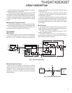
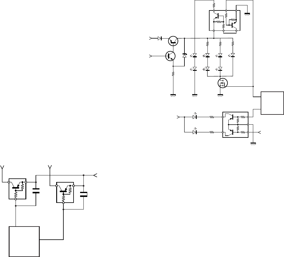
■ LED Drive Circuit
The LCD and key illumination LEDs are lighted by controlling
Q51 for the LCD and Q50 for keys according to the output
voltage from the AF/LAMP AVR (Q37).
The BUSY and TX illumination LEDs are lighted by controlling
Q47.
B
AF AMP
D33
Q38
Q37
56
LAMP
IC8
MPU
99
RX LED
D48
D49
D42
D43
D46
Q50
D41
BUSY LED
R227
D40
TX LED
R226
5C
5T
D42
D43
Q51
Q47
D42
D43
D44
D47
Fig. 13 LED drive circuit
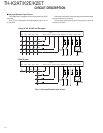
CIRCUIT DESCRIPTION