


TH-K2AT/K2E/K2ET
6
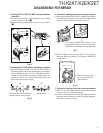
CIRCUIT DESCRIPTION
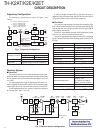
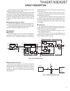
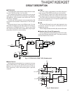
Frequency Configuration
The frequency configuration is shown in Figure 1 and
Table 1.
Fig. 1 Frequency configuration
174.850~212.845MHz
(K,K2,M,M2)
182.850~184.845MHz
(E,E3)
144.000~147.995MHz(K,K2)
136.000~173.995MHz(M,M2)
144.000~145.995MHz(E,E3)
136.000~173.995MHz(K,K2,M,M2)
144.000~145.995MHz(E,E3)
144.000~147.995MHz(K,K2)
136.000~173.995MHz(M,M2)
144.000~145.995MHz(E,E3)
RX :
TX :
ANT
SW
MCF
38.85MHz
38.4MHz
12.8MHz
450kHz
CF
MIX, IF,
DET
AF
AMP
SP
PRE
DRIVE
FINAL
TCXO
DRIVE
Tripler
x 3
RF
AMP
1st MIX
PLL
VCO
MIC
AMP
MIC
ANT
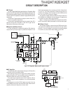
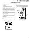
Receiver System
■ Front End
The received signal from the antenna passes through a low-
pass filter and then through a transmission/reception switching
circuit (antenna switch) and enters the band-pass filter (L40,
L41, L38).
The signal passing through the band-pass filter (L40, L41,
L38) is amplified by with an RF amplifier (Q17), passes through
a band-pass filter (L32, L35) and enters the first mixer (Q16).
These band-pass filters are tuned to a desired frequency
by varicaps (D21, D20, D19, D18).
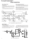
Double super heterodyne
Reception method 1st IF Frequency 38.85MHz (Upper)
2nd IF Frequency 450kHz (Lower)
Transmission method
VCO direct oscillation amplification
Modulation Variable reactance phase modulation
Table 1 Basic configuration
ANT
SW
SP
LPF
VCO
BPF/APC
MPU
IC8
PLL
IF AMP,
DET
Tripler
x 3
TCXO
BPF
L41,L40,L38
BPF
L32,L35
MIXER
Q16
1st Local OSC
(PLL)
RF AMP
Q17
ANT
MCF
XF1
IF AMP
Q24
FM IC
IC3
Q23
2nd Local OSC
X1
AF AMP
IC6
5R5R
D20D21
LV
6
Tuning voltage
D18
38.85MHz
12.8MHz
D19
A tuning voltage corresponding to the desired signal is
applied to each varicap through the BPF/APC terminal (pin 6)
of the MPU (IC8) to tune to the receive frequency.
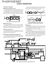
■ First Mixer
The received signal passing through the band-pass filter
(L32, L35) is mixed with the first local signal generated by the
VCO by the first mixer (Q16) to produce a first IF signal (38.85
MHz) (Upper heterodyne).
The first IF signal passes through a MCF (Monolithic crystal
filter: XF1) to remove unwanted components.
The first IF signal passing through the MCF (XF1) is amplified
by an IF amplifier (Q24) and the resulting signal enters the FM
IC (IC3).
Fig. 2 Receiver section configuration
Item Rating
Nominal center frequency (fo) 38.85MHz
Pass bandwidth ±6.0kHz or more at 3dB
Attenuation bandwidth ±25kHz or less at 35dB
Ultimate attenuation 70dB or more (fo –910 kHz)
Spurious response 40dB or more (fo +1MHz)
Ripple 1dB or less
Insertion loss 4dB or less
Terminating impedance 610Ω ±5% // 3pF ±0.5pF
Table 2 MCF (L71-0619-05) characteristics (TX-RX unit XF1)
Item Rating
Nominal center frequency (fo) 450kHz
3dB bandwidth ±6.5kHz or more
50dB bandwidth ±15.5kHz or less
Ripple 2dB or less (fo ±6.5kHz)
55dB or more
Guaranteed attenuation (fo ±18kHz to ±33kHz)
50dB or more (fo
±
100kHz)
Insertion loss 4dB or less
I/O matching impedance 1.5kΩ
Table 3 Ceramic filter (L72-0968-05) characteristics (TX-RX unit CF1)