


TH-K2AT/K2E/K2ET
27
ADJUSTMENT
Single Tone Mode
This mode is used to check the DTMF deviation.
Operation
■ 16key (K, K2, M, M2 and E3 types)
1. Press the [PTT] key on the transceiver to switch to the
transmission mode.
2. Press the [MONI] key to enter the single tone mode.
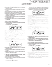
3. Press any key from [1] to [8] keys to transmit a single tone.
The single tone is consisting of eight frequencies.
[1] 697Hz
[2] 770Hz
[3] 852Hz
[4] 941Hz
[5] 1209Hz
[6] 1336Hz
[7] 1477Hz
[8] 1633Hz
4. When the [MONI] key is pressed again during the
transmission, the transceiver switches to the reception
mode, the single tone mode turns OFF.
■ 4key (E type)
1. Press the [PTT] key on the transceiver to switch to the
transmission mode.
2. Press the [MONI] key to enter the single tone mode.
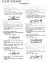
3. When the [VFO] key is pressed during the transmission, a
DTMF “D” dual tone (combination of 1633 Hz and 941 Hz
frequencies) is transmitted.
4. When the [MR] key is pressed during the transmission,
single-tone 1633 Hz is transmitted.
5. When the [MONI] key is pressed again during the
transmission, the transceiver switch to the reception mode,
the single tone mode is turned OFF.
• The single tone mode can be enabled only during the
transmission.
• When DTMF memory is transmitted in the single tone
mode, the single tone mode turns OFF.
Adjustment Mode
This mode is used to replace or readjust the IC15 (EEPROM).
Adjust the following adjustment items after setting the
transceiver to “Adjustment Mode”.
■ Adjustment Items
A. Overvoltage warning reference voltage (14.8V [DC IN])
B. Battery terminal reference voltage (7.5 V [Battery terminal])
C. Squelch (SQL1, SQL2)
D. S-meter (Two segments in S-meter light, all segments in S-
meter light)
E. RX BPF (Lower limit frequency, center frequency, upper
limit frequency)
F. 7.5V TX H power (Lower limit frequency, center frequency,
upper limit frequency)
G. 7.5V TX M power (Lower limit frequency, center frequency,
upper limit frequency)
H. 7.5V TX L power (Lower limit frequency, center frequency,
upper limit frequency)
I. 13.8V TX H power (Lower limit frequency, center frequency,
upper limit frequency)
J. 13.8V TX M power (Lower limit frequency, center frequency,
upper limit frequency)
K. 13.8V TX L power (Lower limit frequency, center frequency,
upper limit frequency)
L. DCS modulation balance
M.Tone deviation (Lower limit frequency, center frequency,
upper limit frequency)
N. DCS deviation (Lower limit frequency, center frequency,
upper limit frequency)
O. VOX sensitivity (Level 1, level 9)
■ Operation in Adjustment Mode
1. Turn the transceiver ON.
2. Set the tone frequency to 151.4 Hz and the DCS code to
023 in Menu Mode to adjust tone and DCS modulation.
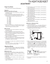
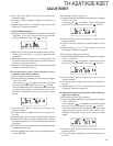
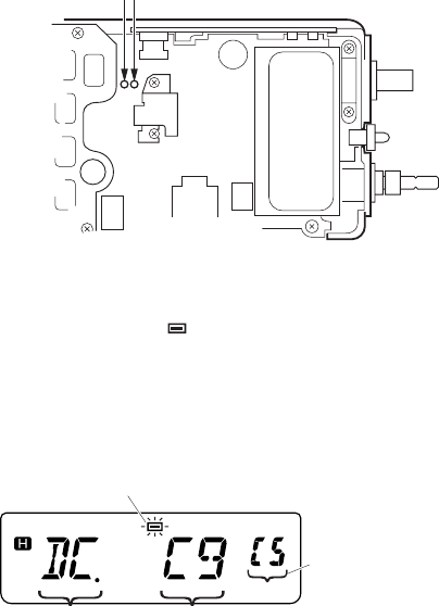
3. Set Adjustment Mode by shorting two lands (SET) on the
component side of the TX-RX unit (A/3).
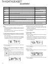
4. When the Adjustment Mode is set, the “Overvoltage
warning reference voltage (14.8V [DC IN])” adjustment item
is displayed. (The “
” icon on the upper side of the LCD
blinks while the transceiver is in the Adjustment Mode.)
The current adjustment value is displayed at the lower digits
of the frequency display, and the value stored in the
EEPROM is displayed on the memory channel number
display.
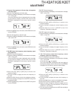
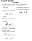
5. The functions of transceiver keys in Adjustment Mode are
as follows:
Short these two lands
SET
Adjustment item
Blink
The value stored in the
EEPROM. (00-FE)
Current adjustment
value (00-FE)