


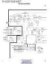


TH-K2AT/K2E/K2ET
55
BPF
Q9
Q11
Q16
Q10
Q12
Q17
BPF
Q24
MIC AMP
vco
ANTFILTER
50Ω
ANT
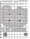
9.74Vrms 0.84Vrms -18.68dBm 10.50dBm 4.17dBm 15.17dBm 11.00dBm 24.67dBm 20.83dBm 30.50dBm
AF(1kHz) RF(145.99MHz)
ANTFILTER
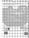
-59.33dBm-62.50dBm -31.83dBm-47.83dBm
vco
-35.83dBm -17.33dBm
FM IC
IC3 IC6
AMP
RF(145.99MHz) AF(1kHz)IF(38.85MHz)
-53.00dBm 0.26Vrms 12.09mVrms 0.66Vrms
0.58Vrms
MIC
ANT SP
-9.83dBm
IC16
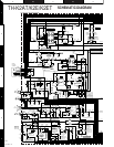
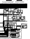
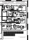
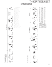
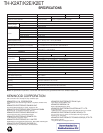
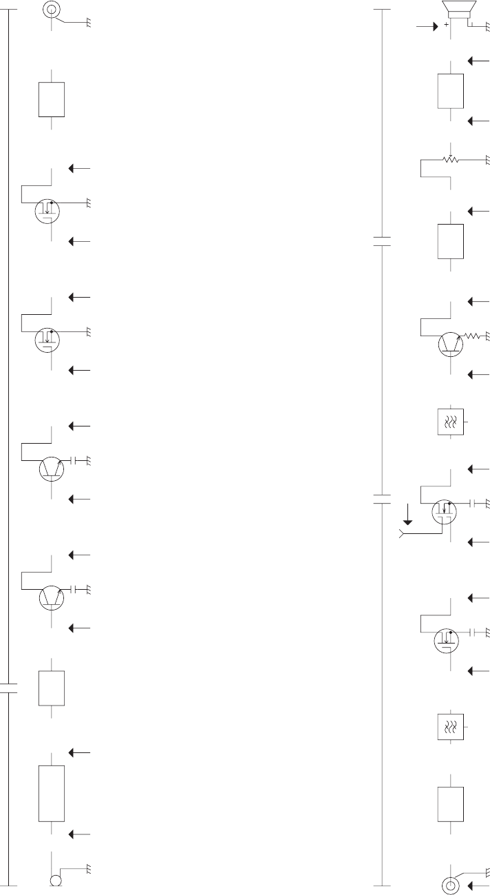
LEVEL DIAGRAM
All voltage levels must be measured at High power transmission.
The RF and IF sections are measured by using a spectrum analyzer.
After setting the standard (1 kHz, 3 kHz Dev.) deviation, each voltage
of the AF section is measured by using an AF VTVM or osciloscope.
The level for each point is measured without removing parts or cutting
the pattern.
All voltage levels must be measured after setting the AF output volt-
age at 0.58V rms.
The RF and IF sections are measured by using a spectrum analyzer.
Each voltage of the AF section is measured by using an AF VTVM or
osciloscope.
The level for each point is measured without removing parts or cutting
the pattern.
Transmitter Section
Receiver Section