5
6. Route the transducer cable to the sonar unit. If possible, route the
transducer cable away from other wiring on the boat. Electrical noise
from the engine’s wiring, bilge pumps, VHF radio wires and cables,
and aerators can be picked up by the sonar. Use caution when routing
the transducer cable around these wires.
IMPORTANT!
Clamp the transducer cable to the transom close to the transducer. This
can prevent the transducer from entering the boat if it is knocked off at
high speed.
7. Make a test run to determine the results. If the bottom is lost at high
speed, or if noise appears on the display, try sliding the transducer
bracket down. This puts the transducer deeper into the water, hope-
fully below the turbulence causing the noise. Do not allow the trans-
ducer bracket to go below the bottom of the hull!
SONAR UNIT MOUNTING
Install the X-70A 3D in any convenient location, provided there is clear-
ance behind the unit when it is tilted for the best viewing angle. Holes in
the bracket base allow wood screw or through-bolt mounting. Make cer-
tain there is enough room behind the unit to attach the power and trans-
ducer cables.
Using the bracket as a template, mark the dash for the mounting holes,
then make a mark in the center of the bracket location for the cable hole.
If you want the smallest possible hole for the power and transducer cables
in the dash, install the transducer first, then route the cable to the desired
location. The smallest hole that will pass one power or transducer plug is
5/8". After the hole is drilled, pass the transducer connector up through
the hole first, then pass the power cable down through it.
After routing the cables, fill the hole with a good marine sealing com-
pound. Place the bracket over the hole and route the cables through the
slot in the back of the bracket. Break out one of the other slots for the
transducer cable. Screw the bracket to the dash.
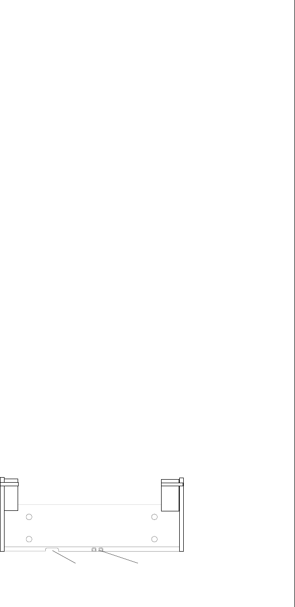
FRONT
SLOT
BREAK OUT SLOT


