


H2iSD-14
2010 Hyper-heating Y-SERIES SYSTEM DESIGN (Sept. 2010)
2010 H2i
®
Y-SERIES
SYSTEM DESIGN
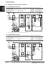
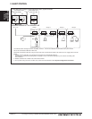
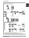
2. M-NET CONTROL
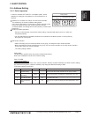
2. Address should be set to Indoor units and central controller.
3. For a system having more than 16 indoor unit, confirm the need of Booster at 2-3 "System configuration restrictions".
NOTE:
1. Outdoor units OC and OS in one refrigerant circuit system are automatically detected.
OC and OS are ranked in descending order of capacity. If units are the same capacity, they are ranked in ascending order
of their address.
Indoor unit
MA R/C MA R/C MA R/C
(Main) (Sub)
MA R/C
SRU
Wireless R/C
*3
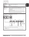
*3 For Wireless R/C and Signal receiver unit (SRU), channel 1, 2 and 3 are selectable and should be set to same channel.
*SC can be connected to TB3 side or TB7 side;
Should SC connected to TB7 side, change Jumper from CN41 to CN40 at the Outdoor unit module so as to supply power to the SC.
*3
01 02 03 04 05
TB15
TB5 TB5TB5 TB5 TB5
TB15 TB15 TB15 TB15
*1 *2
201
SC
To *1 or *2
Group 2Group 1 Group 3 Group 4
TB3TB3
5251
OC OS
PUHY-HP-TSJMU
TB3
51
OC
CN41CN40CN41CN40 CN41CN40
ON
DipSW2-1
ON
DipSW2-1
ON
DipSW2-1
PUHY-HP-TJMU
<Two outdoor units>
<One outdoor unit>
2-4-3-2. MA remote controller, Single-refrigerant-system, System Controller