


2010 Hyper-heating Y-SERIES SYSTEM DESIGN (Sept. 2010)
H2iSD-35
2010 H2i
®
Y-SERIES
SYSTEM DESIGN
4. OUTDOOR INSTALLATION
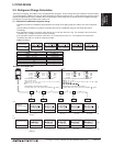
4-5. Low Ambient Kit Application Guidelines
General Unit Placement and Clearances
• Outdoor units should be located in an area protected from
prevailing winds.
• In high wind locations, it may be advisable to install the outdoor
units within a walled area.
• Hood discharge should be directed away from or perpendicular
to the prevailing winds. Do not direct the hood discharge towards
prevailing winds.
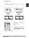
• When using the low ambient components, add an additional 7” to
the standard mounting clearances.
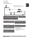
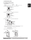
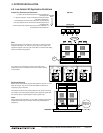
Equipment Supports
When modules are combined, they should be placed a minimum of 1-3/16”
apart.Bydoingso,onlyonesetofsidewinddeectors(SWD-1)are
required per group of modules.
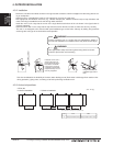
Theequipmentsupportmustbermlyattachedtothegroundorstructure.
The outdoor unit must be properly attached to the equipment support with
3/8” stainless steel or equal strength to at least a grade 5 bolt.
Note:
If the outdoor unit is located in an area with continuous high winds,
additional braced may be required. Contact your distributor for
assistance.
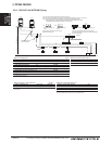
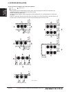
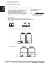
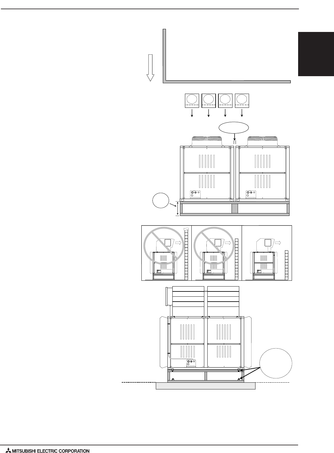
Top View
Prevailing
Wind
Outdoor Units
Building Wall
12"
1-3/16"
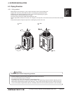
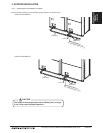
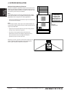
Note:
Equipment supports must elevate the unit at least 12” above the average
expected snow depth or 12” above the ground, whichever is higher. The
equipment supports must be an open construction to minimize snow drifting
and/or ice formation during defrost.
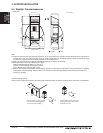
OK
If the units are surrounded by an enclosure, the hood must be
positioned that the air is directed out and over the walls to prevent
air recirculation.
Minimum 3/8”
stainless steel or
harder bolts
Concrete Pad