


2010 Hyper-heating Y-SERIES SYSTEM DESIGN (Sept. 2010)
H2iSD-31
2010 H2i
®
Y-SERIES
SYSTEM DESIGN
4. OUTDOOR INSTALLATION
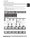
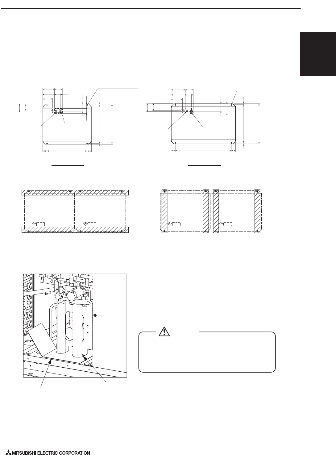
4-3-5. Refrigerant pipe routing
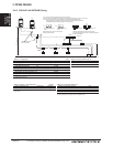
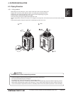
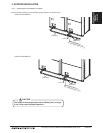
4-3-4. Installation
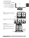
Installation base perpendicular to the unit’s front panelInstallation base parallel to the unit’s front panel
When the pipes and/or cables are routed at the bottom of the unit, make sure that the through hole at the base of
the unit does not get blocked with the installation base.
When the pipes are routed at the bottom of the unit, the base should be at least 100 mm [3-15/16 in] in height.
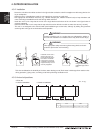
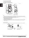
The gaps around the edges of through holes for pipes and wires on the
unit allow water or mice to enter the unit and damage its parts. Close
these gaps with filler plates.
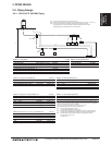
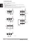
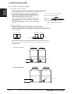
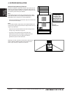
This unit allows two types of pipe routing:
• Bottom piping
• Front piping
To prevent small animals, water and snow from
entering the unit and damage its parts, close the
gap around the edges of through holes for pipes
and wires with filler plates.
CAUTION
Example of closure materials (field-supplied)
Fill the gap at the site
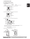
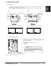
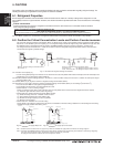
· HP72
Bottom view
· HP96
(Unit : mm [in.]) (Unit : mm [in.])
Refrigerant service
valve <liquid>
(Mounting pitch)
(Mounting pitch)
Refrigerant service
valve <gas>
(5-29/32)
150
18
18
(28-17/32)
(5-23/32)
(3-5/8)
(3-13/32)
(3-9/32)
(5-29/32)
(7-11/32)
(8-23/32)
(9-29/32)
(5-3/16)
(3-5/32)
(29-15/16)
(3-5/32)
(23/32)
(28-13/32~28-5/8)
(29-15/16)
(23/32)
2X2-14(9/16)X20(13/16) Oval hole
221
150
145
83
(760)
80
760
80
724(721~727)
92
86
131
251
186
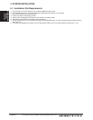
Refrigerant service
valve <gas>
Refrigerant service
valve <liquid>
(Mounting pitch)
(Mounting pitch)
301 83
(5-29/32)
150
760
18
724(721~727)
(29-15/16)
(28-13/32~28-5/8)
(28-17/32)
(23/32)
2X2-14(9/16)X20(13/16) Oval hole
(3-23/32)
(3-5/16)
(5-23/32)
(3-9/32)
(5-29/32)
(5-3/16)
(11-7/8)
(10-11/16)
(8-17/32)
(41-3/4)
(3-5/32) (3-5/32)
(23/32)
150271
94 84
145
216
18
8080
1060
131
Bottom view