


1. INTRODUCTION
1 - 3
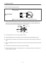
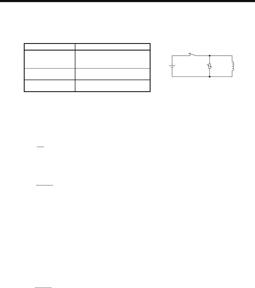
(3) Selection of surge absorbers for electromagnetic brake circuit
The following shows an example how to select a varistor with a surge absorber.
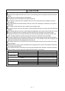
(a) Selection conditions
Item Condition
Electromagnetic brake
specification
R [Ω]: Resistance
L [H]: Inductance
Vb [V]: Power supply voltage
Desired suppression
voltage
Vs [V] or less
Durable surge
application time
N times
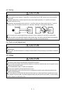
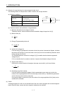
24 V DC
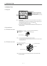
Rela
y
Brake coil
U
Varistor
(b) Tentative selection and verification of surge absorber
1) Maximum allowable circuit voltage of varistor
Tentatively select a varistor whose maximum allowable voltage is larger than Vb [V].
2) Brake current (Ib)
Ib =
Vb
R
[A]
3) Energy (E) generated by brake coil
E =
2
L × lb
2
[J]
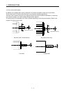
4) Varistor limit voltage (Vi)
From the energy (E) generated in the brake coil and the varister characteristic diagram, calculate
the varistor limit voltage (Vi) when the brake current (Ib) flows into the tentatively selected varistor
during opening of the circuit.
Vi is favorable when the varistor limit voltage (Vi) [V] is smaller than the desired suppressed
voltage (Vs) [V].
If Vi is not smaller than Vs, reselect a varistor or improve the withstand voltage of devices.
5) Surge current width (τ)
Given that the varistor absorbs all energies, the surge current width (τ) will be as follows.
τ =
E
Vi × lb
[S]
6) Examining surge life of varister
From the varistor characteristic diagram, find the guaranteed current value (Ip) in which the
number of the surge application life is N at the surge current width (τ). Calculate the guaranteed
current value (Ip) ratio to brake current (Ib).
If an enough margin is ensured for Ip/Ib, the number of the surge application life N [time] can be
considered as favorable.
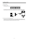
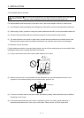
(4) Others
A leakage magnetic flux will occur at the shaft end of the servo motor equipped with an electromagnetic
brake. Note that chips, screws and other magnetic substances are attracted.