


5. WIRING OPTION
5 - 7
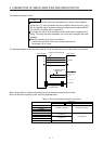
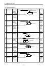
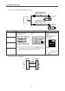
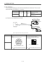
(a) Connection of servo amplifier and servo motor
2)
1)
Servo motor
HF-KN
MR-J3ENCBL_M-A2-L
MR-J3ENCBL_M-A2-H
2)
1)
Servo motor
HF-KN
MR-J3ENCBL_M-A1-L
MR-J3ENCBL_M-A1-H
or
CN2
Servo amplifier
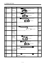
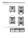
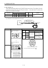
Cable model 1) CN2-side connector 2) Encoder-side connector
Receptacle: 36210-0100PL
Shell kit: 36310-3200-008
(3M or equivalent)
Connector set: 54599-1019
(Molex)
MR-J3ENCBL_M-A1-L
MR-J3ENCBL_M-A1-H
1
P5
3
MR
79
4
MRR
2
LG
8610
5
View seen from wiring side. (Note)
or
4
MRR
2
LG 8
6
1
P5
5
10
3
MR
7
9
View seen from wiring side. (Note)
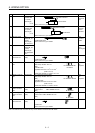
MR-J3ENCBL_M-A2-L
Connector: 2174053-1
Crimping tool for ground clip:
1596970-1
Crimping tool for receptacle
contact: 1596847-1
(TE Connectivity)
9
SHD
7
5MR
3P5
1
8
6LG
4
MRR
2
View seen from wiring side.
(Note)
MR-J3ENCBL_M-A2-H
Note. Do not connect anything to the pins shown as
. Especially, pin
10 is provided for manufacturer adjustment. If it is connected with any
other pin, the servo amplifier cannot operate normally.
Note. Do not connect anything
to the pins shown as
.
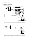
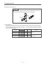
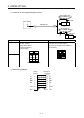
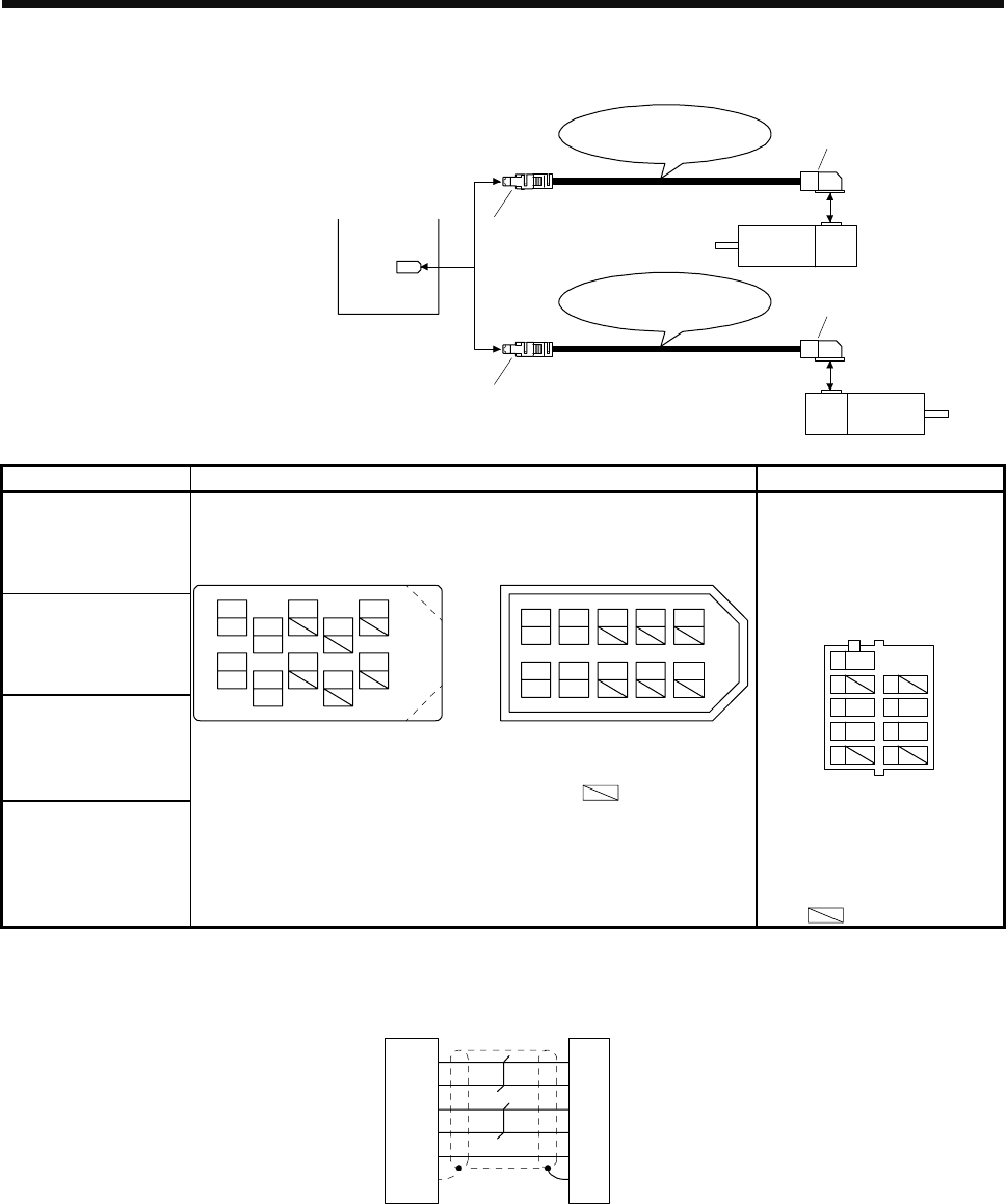
(b) Cable internal wiring diagram
P5
LG
1
2
MR
MRR
3
4
2
3
CN2-side
connector
Encoder-side
connector
9
SD
Plate
5
4
6
9
LG
MR
MRR
SHD
P5