


4. CONNECTION OF SERVO AMPLIFIER AND SERVO MOTOR
4 - 5
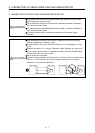
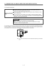
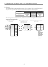
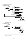
4.2.2 HF-SN series servo motor
Refer to section 4.3 for the wires used for wiring.
(1) Wiring
(Note 3)
RA3
Servo motorServo amplifier
M
U
V
W
U
V
W
50 m or less
(Note 4) CNP2
(Note 1)
B1
B2
(Note 2)
24 V DC power supply
for electromagnetic
brake
ALM
(Malfunction)
RA1
MBR
(Electromagnetic
brake interlock)
RA2
U
B
Note 1. There is no polarity in electromagnetic brake terminals (B1 and B2).
2. Do not use the 24 V DC interface power supply for the electromagnetic brake.
3. Create the circuit in order to shut off by interlocking with the emergency stop switch.
4. The name and shape of connector differ depending on the servo amplifier types.