


GB114BS/BP GLOBUG LIGHTING SYSTEM • OPERATION AND PARTS MANUAL — REV. #3 (01/06/09) — PAGE 15
COMPONENTS
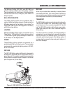
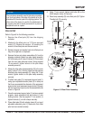
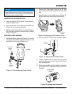
Figure 5 shows the location of the components for the
GloBug lighting system. The function of each component
is described below:
Lamp Guard 1. — This guard (cage) protects the lamp
from being hit by objects.
Lamp 2. — 1000 watt metal-halide type lamp. Replace
only with MQ recommended type lamp. Always allow
a suffi cient amount of time for the lamp to cool down
before changing.
Fan Motor (Blower) 3. — This electric motor is
responsible for infl ating the balloon. It will supply a
pressure of 31.26 psi /215.6 kPA. Please note that the
balloon will begin to infl ate as soon as power is applied
to the lighting system.
Balloon Cover/Carrying Case 4. — When zipped, this
protective cover acts like a carrying case. The complete
lamp assembly is enclosed within the cover-carrying
case. Allow a suffi cient amount of time for the lamp
to cool down before covering balloon. The possibility
exists of the balloon getting burned.
Lamp Assembly Connector 5. — Quick-disconnect
cable. Provides AC power to lamp assembly.
T-Handle Bolt Lock 6. — Always tighten this lock to hold
the lamp/balloon securely in place.
Balloon 7. — This balloon is made of heat-resistant
nylon, with a diameter of 47 inches (1200 mm).
Offset Pole 8. — Supports lamp assembly when attached
to the main mast. Included with the offset pole is a
17/19 mm wrench.
Lamp Power Cable (Output) 9. — Connect this cable
between the ballast receptacle and the lamp assembly
connector.
Pole Clamps 10. — Attach these clamps (2) to the
main pole and external support pole. Always tighten
both clamps securely to prevent slippage of the light
assembly.
Main Pole 11. — Used in conjunction with the offset pole
to support the lamp assembly.
Ballast 12. — Power source for lamp. Input power
requirements are 120 VAC, 60 Hz @9.5 amps.
Ballast AC Power Cable (Input) 13. — Connect this cable
to a 120 VAC, 60 Hz power source.