


PAGE 16 — GB114BS/BP GLOBUG LIGHTING SYSTEM • OPERATION AND PARTS MANUAL — REV. #3 (01/06/09)
SETUP
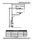
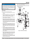
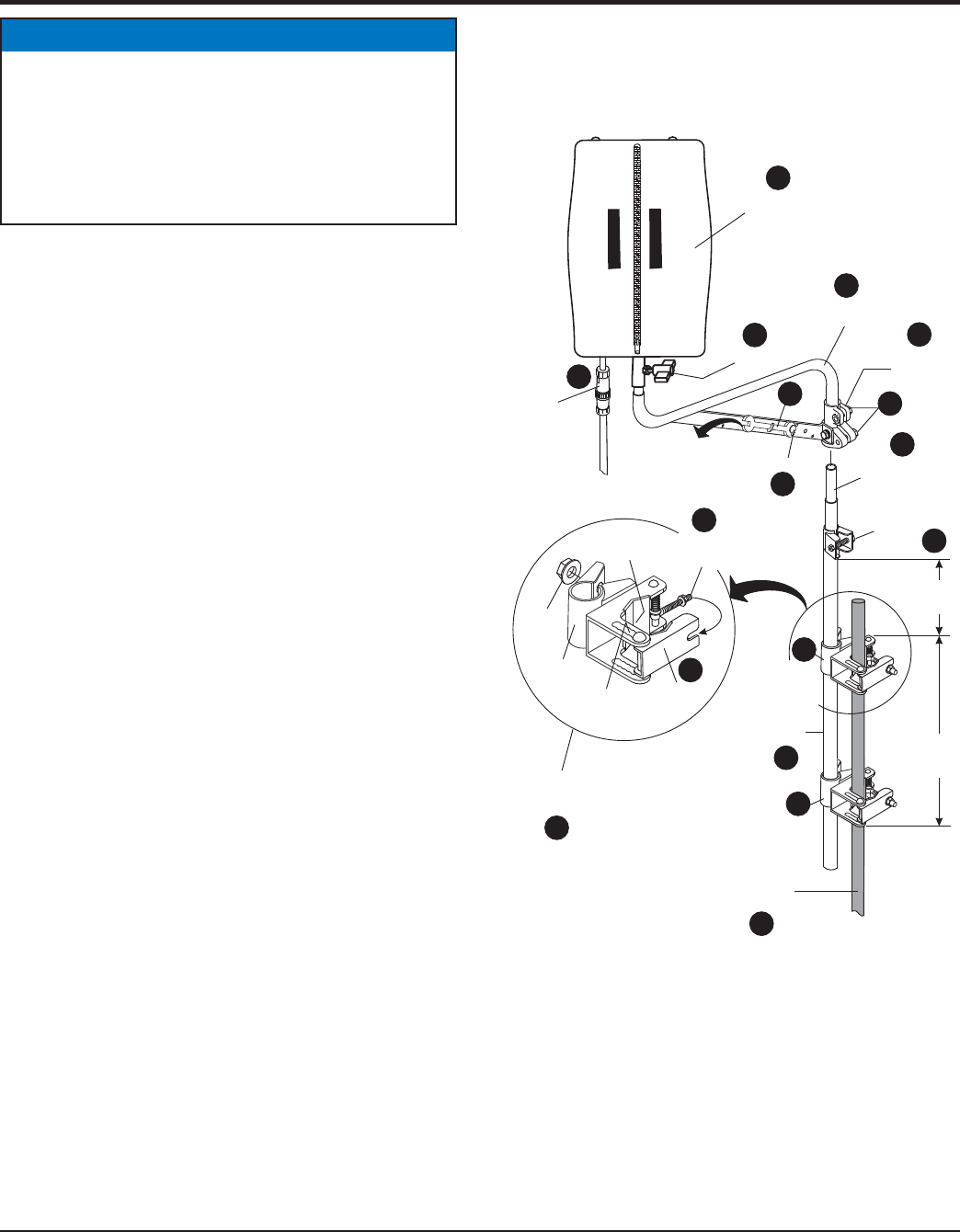
POLE SETUP
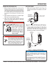
Refer to Figure 6 for the following procedure.
Remove the offset pole (B) from the shipping 1.
container.
Attached to the offset pole is a 17/19 mm open-end 2.
wrench (C). Remove the wingnut (D) securing the
wrench to the offset pole and remove wrench.
Reinsert wingnut and washer back into offset pole so 3.
they will not get lost or misplaced.
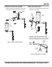
Remove the two pole clamp assemblies (A) from the 4.
shipping container. Attach one pole clamp assembly
(E) to the main pole (F) about 3 inches (76.2 mm) down
from the main pole extension clamp. Using supplied
19 mm wrench, tighten locknut on the pole clamp
assembly securely.
Attach the other pole clamp assembly (G) to the main 5.
pole (F) about 7.0 in. (140 mm.) down from the previous
attached pole clamp assembly (E). Using the 19 mm
wrench, tighten locknut on the pole clamp assembly
securely.
To attach main pole (F) to equipment support pole (I), 6.
swing open adjustable tension plate (H) on clamp so
that it can accomodate the diameter of the equipment
support pole. Insert equipment support pole (I) through
the two equipment support pole clamp assemblies as
shown in Figure 6.
Once the equipment support pole (I) has been seated 7.
properly, move adjustment bolt and locknut (J) into
locking position. Use the supplied 17 mm wrench, to
tighten locknuts (J) on both clamps securely.
Place offset pole (B) with adapter clamp (K) on top of 8.
adjustable extension pole (L). Make sure that offset
pole has been seated correctly.
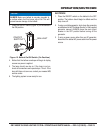
NOTICE
The pole clamp assembly used in this setup procedure
is a dual type clamp. One side of the clamp is for the
attachment of the main pole of the lighting system. The
other side of the clamp is used for the attachment of
a support pole that is usually connected to a piece of
equipment such as a paver.
Using 17 mm wrench, tighten both bolts (M) on the 9.
offset adapter clamp (K) securely.
Place lamp assembly (N) onto offset pole (B). Tighten 10.
T-handle bolt (O) securely.
Offset Pole AssemblyFigure 6.
T-HANDLE
LAMP
ASSEMBLY
OFFSET
POLE
ADJUSTABLE
EXTENSION
POLE
EQUIPMENT
SUPPORT
POLE
MAIN POLE
CLAMP
ADJUSTABLE
CHANNEL
ADJUSTMENT
BOLTAND
LOCKNUT
MAIN
POLE
7.0 IN.
(140 M
M
3.0 IN.
(76.2 M
M
EXTENSION
CLAMP
BOLT
REMOVE
WRENCH
C
WINGNUT
E
G
POLE
CLAMP
ASSY.
LOCKNUT
EQUIPMENT
SUPPORT
POLE CLAMP
M
OFFSET
ADAPTER
CLAMP
O
BALLOON
POWER
CABLE
P
B
D
L
F
POLE
CLAMP
ASSEMBLY
TENSION
PLATE
I
K
N
Q
A
POLE
CLAMP
ASSY.
J
H