


PAGE 28 — GB114BS/BP GLOBUG LIGHTING SYSTEM • OPERATION AND PARTS MANUAL — REV. #3 (01/06/09)
VOLTAGE MEASUREMENTS
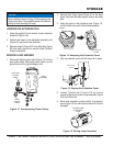
VOLTAGE MEASUREMENT (BALLAST NO-LOAD)
Remove lamp from pipe frame as refrenced in 1.
maintenance section of this manual.
Place lamp in a safe place where it will not get damaged 2.
or broken.
Apply 120 VAC power to the ballast. Place ballast ON/3.
OFF switch in the ON position.
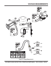
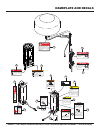
Using a multimeter (Figure 32) measure the output 4.
voltage at the ballast receptacle. Pins 1-3 (lamp) should
read between 380~465 VAC. Pins 1-2 (fan motor)
should read 120 VAC.
Place the ballast ON/OFF switch in the OFF position.5.
VOLTAGE MEASUREMENT (LAMP CABLE NO-
LOAD)
Connect the male end of the lamp power cable to the 1.
ballast female receptacle.
Place ballast ON/OFF switch in the ON position.2.
Using a multimeter measure the output voltage at the 3.
female end of the of the lamp power cable. Pins 1-3
(lamp) should read between 380~465 VAC. Pins 1-2
(fan motor) should read 120 VAC.
If voltage is not present, replace lamp power cable. 4.
Make sure connection at ballast end of cable is tight
and secure (locked).
Place the ballast ON/OFF switch in the OFF position5.
DANGER
Be careful when performing voltage measurements.
The possiblity exists of electrical shock if fi ngers make
contact with connector pins, thus causing bodily harm
or even death.
NEVER allow multimeter test leads to make contact
with each other. The possibility exists of electrical short
causing severe damage to the equipment, bodily
harm, electrocution, and even death!
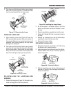
VOLTAGE MEASUREMENT (LAMP SOCKET NO-
LOAD)
Connect the female end of the lamp power cable to 1.
the male power connector that is attached to the lamp
assembly.
Place ballast ON/OFF switch in the ON position.2.
Using a multimeter, place one test lead on the lamp 3.
socket tab, place the other lead on the threaded portion
of the socket.
A voltage between 380~465 VAC should be present 4.
between lamp socket tab and threaded portion of the
lamp socket. If the voltage is not present, check wiring
inside pipe frame and lamp socket.
Place the ballast ON/OFF switch in the OFF position.5.
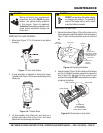
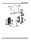
VOLTAGE MEASUREMENT (FAN MOTOR)
Make sure the lamp power cable is securely connected 1.
between the ballast receptacle and the lamp assembly
power connector.
Place the ballast ON/OFF switch in the OFF position. It 2.
is not required for the fan motor test measurement.
Apply 120 VAC power to the ballast and listen for the 3.
whirring sound of the fan motor. This sound will indicate
that the fan motor is running.
If the fan motor is not running, use a multimeter and 4.
place one test lead on the black wire and the other lead
on the blue wire as shown in Figure 32.
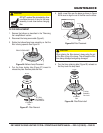
Additional voltage check can me made at the fan motor 5.
capacitor. Place the multimeter test leads across the
tabs on the capacitor. A voltage of approximately 208
VAC should be measured. If 208 VAC is not present
check or replace capacitor.
NOTICE
You may have to use test leads that can prick the wire
insulation. The voltage measured should be 120 VAC.
If 120 VAC is not present check wiring inside pipe
frame.