


14 DS400 and DS500 Digital Fishfinders
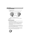
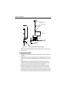
The RED wire must be connected to the feed from the positive (+) battery
terminal and the BLACK wire to the feed from the negative (–) battery
terminal.
A fast blow 2 amp fuse is installed in-line on the red (positive) wire.
CAUTION:
If the power connections are accidentally reversed the system will not
work. Use a multimeter to ensure that the input power leads are
connected for correct polarity.
Transducer Connection
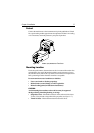
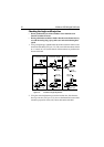
A 25ft (8m) cable is supplied with the transducer. The transducer cable
connector has a nut that has been removed to aid installation. To enable you
to complete the installation without cutting the cable, ensure that any holes
you drill are large enough to accept the connector, with the nut removed
(approximately 13/16" or 21 mm).
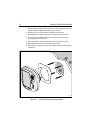
Before attaching the transducer cable, you will need to attach the connector
nut, which is included in the transducer packaging.
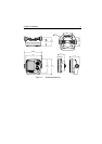
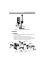
The transducer cable is attached to the 7 pin male TRANSDUCER connector on
the connector panel of the DS400/500. (See Figure 2-5 .)
CAUTION:
• Do not pull on the cable. This can damage the transducer wires.
• Do not cut the transducer cable or remove the connector.
• Do not try to shorten or splice the cable. Cutting the transducer cable will
severely reduce sonar performance.
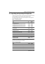
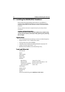
Pin No. Function Color
1 Battery negative – Black
2 Battery positive + (10.0VDC to 18.0VDC) Red
3 NMEA Input + White
4NMEA Input – Green
5 CGND Gray
6 NMEA Output + Yellow
7NMEA Output – Brown