


1-5
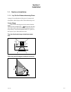
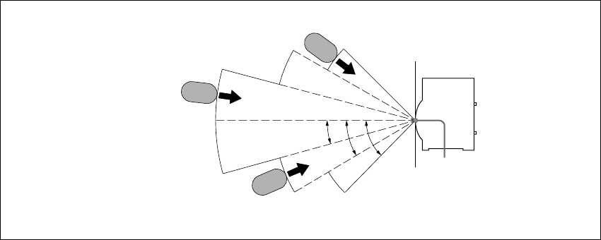
PCS-1/1P
45d
30d
Infrared
light emitter
Infrared
light emitter
Infrared
light emitter
5 m
15d
3.5 m 2.5 m
Infrared
photosensor
PCS-1/1P
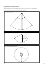
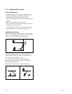
b. Installation range (Reference)
If an image is disturbed in the range shown below, bring it near PCS-1/1P with the infrared light
emitter of a documents stand turned toward PCS-1/1P.
m
. Install so that the infrared light emitter of a document stand is linear in direction with the infrared
photosensor of PCS-1/1P. Do not put an object that interrupts transmission. When the direction of the
infrared light emitter is shifted by five degrees or more, normal reception cannot be carried out, that is,
an image is disturbed or stands still.
. Multiple document stands cannot be used at the same time. Infrared rays interfere and any signal
cannot be received.
. The resolution of an image deteriorates when a video signal is transmitted using an infrared video
transmission function. Connect the infrared light emitter with PCS-1/1P using a MONITOR OUT
terminal when you do not want to deteriorate the resolution.
. Connect the infrared light emitter with PCS-1/1P using a MONITOR OUT terminal when an infrared
video transmission function cannot be used due to the situation of a videoconferencing room.
. An image may be disturbed when other infrared light emitters are used or when a remote controller is
used near the photosensor. Stop the use of other infrared light emitters or connect them with PCS-1/1P
using a MONITOR OUT terminal.