


10
output is provided at the Y1 connection. Connect the solenoid as
shown in the wiring label diagram. This is a 24vac output that is
energized whenever the compressor is energized. It closes, in the
compressor off mode, to prevent refrigerant migration into the unit
through the liquid--line.
On Systems with Accessory Liquid Solenoid Using a
Non--Communicating Thermostat: The liquid solenoid is
connect to the Y1 and C terminal connections. The liquid solenoid
closes, in the compressor off mode, to prevent refrigerant migration
into the unit through the liquid --line.
Check Charge
Charged in high or low stage
Factory charge amount and desired subcooling are shown on unit
rating plate for high stage. Char ging method is shown on
information plate inside unit. To properly check or adjust charge,
conditions must be favorable for subcooling charging. Favorable
conditions exist when the outdoor temperature is between 70_F
and 100_F (21.11_C and 37.78_C), and the indoor temperature is
between 70_F and 80_F (21.11_C and 26.67_C). Follow the
procedure below:
Unit is factory charged for 15ft (4.57 m) of lineset. Adjust charge
by adding or removing 0.6 oz/ft (17.74 g/m) of 3/8 liquid line
above or below 15ft (4.57 m) respectively.
For standard refrigerant line lengths (80 ft/24.38 m or less), allow
system to operate in cooling mode at least 15 minutes. If conditions
are favorable, check system charge by subcooling method. If any
adjustment is necessary, adjust charge slowly and allow system to
operate for 15 minutes to stabilize before declaring a properly
charged system.
If the indoor temperature is above 80_F (26.67_C), and the
outdoor temperature is in the favorable range, adjust system charge
by weight based on line length and allow the indoor temperature to
drop to 80_F (26.67_C) before attempting to check system charge
by subcooling method as described above.
If the indoor temperature is below 70_F (21.11_C), or the outdoor
temperature is not in the favorable range, adjust charge for line set
length above or below 15ft (4.57 m) only. Charge level should then
be appropriate for the system to achieve rated capacity. The charge
level could then be checked at another time when the both indoor
and outdoor temperatures are in a more favorable range.
NOTE: If line length is beyond 80 ft (24.38 m) or greater than 20
ft (6.10 m) vertical separation, See Long Line Guideline for
special char ging requirements.
Heating Check Chart Procedure
To check system operation during heating cycle, refer to the Heat
Pump Charging Instructions label on outdoor unit. This chart
indicates whether a correct relationship exists between system
operating pressure and air temperature entering indoor and outdoor
units. If pressure and temperature do not match on chart, system
refrigerant charge may not be correct. Do not use chart to adjust
refrigerant charge.
NOTE: In heating mode, check refrigerant charge only when
pressures are stable. If in doubt, remove charge and weigh in
correct refrigerant charge.
NOTE: When charging is necessary during heating season, charge
must be weighed in accordance with unit rating plate, ±0.6 oz./ft
(±17.74 g/m). of 3/8--in. liquid--line above or below 15 ft (4.57
m)., respectively.
EXAMPLE:
To calculate additional charge required for a 25 --ft. line set:
25 ft. -- 15 ft. = 10 ft. X 0.6 oz./ft. = 6 oz. of additional charge.
MAJOR COMPONENTS
2--Stage Control Board
The HP control board controls the following functions:
S High and low stage compressor contactor operation
S Outdoor fan motor operation
S Reversing valve operation
S Defrost operation
S Low ambient cooling
S Crankcase heater operation
S Compressor external protection
S Pressure switch monitoring
S Time Delays
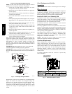
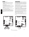
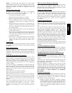
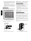
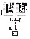
Field Connections
On non--communicating (non --Infinity) system, the two--stage
control r eceives 24vac low--voltage control system inputs through
the R, C, Y1, Y2 and O connections located at the bottom of the
control board (see Fig. 6.) On a non --communicating system,
output W1 is connected at the bottom of the control board for
auxiliary heat.
For a communicating system, use the ABCD Infinity connections.
Two Stage Compressor
The two stage compressor contains motor windings that provide
2--pole (3500 RPM) operation.
Compressor Internal Relief
The compressor is protected by an internal pressure relief (IPR)
which relieves discharge gas into the compressor shell when
differential between suction and discharge pressure exceeds
550--625 psi. The compressor is also protected by an internal
overload attached to motor windings.
Compressor Control Contactor
The contactor has a 24volt coil. The electronic control board
controls the operation of the contactor.
TROUBLESHOOTING
Systems Communication Failure
If communication with the Infinity control is lost with the User
Interface, the control will flash the appropriate fault code. (See
Table 4.) Check the wiring to the User Interface and the indoor and
outdoor units.
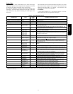
Model Plug
Each control board contains a model plug. The correct model plug
must be installed for or the system to operate properly. (See Table
3.)
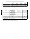
Table 3 – Model Plug Information
MODEL
NUMBER
MODEL PLUG
NUMBER
PIN RESISTANCE
(K---ohms)
Pins 1 --- 4 Pins 2---3
25HPA624 HK70EZ041 18 91
25HPA636 HK70EZ043 18 150
25HPA648 HK70EZ045 18 220
25HPA660 HK70EZ047 18 360
The model plug is used to identify the type and size of unit to the
control.
On new units, the model and serial numbers are input into the
board’s memory at the factory. If a model plug is lost or missing at
initial installation, the unit will operate according to the
information input at the factory and the appropriate error code will
flash temporarily. An RCD replacement board contains no model
and serial information. If the factory control board fails, the model
plug must be transferred from the original board to the replacement
board for the unit to operate.
25HPA6