


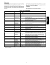
7
Airflow Selection for FV4C Fan Coils Using
Non--Communicating (Non--Infinity) Thermostats
The FV4C provides high -- and low --stage blower operation to
match the capacities of compressor at high-- and low--stage. To
select recommended airflow, refer to FV4C Installation
Instructions. The FV4C utilizes an Easy Select control board that
allows the installing technician to select proper airflows. For
adjustments to control board, select appropriate HP SIZE and CFM
ADJUST setting. This fan coil has an adjustable blower off delay
factory set at 90 sec for high-- and low--stage blower operation.
When using a communicating (Infinity) control, dipswitch
adjustments are not necessary. Airflows are determined by Infinity
Control setup. The fan coil is the FE4A.
For other combinations of equipment consult Product Data Digest.
Install Accessories
Refer to the individual instructions packaged with kits or
accessories when installing.
When using a communicating control with the fan coil or the
furnace, dip switch adjustments are not necessary. The outdoor
unit configuration and the indoor airflows are determined by
communicating control setup.
Start--Up
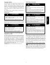
CAUTION
!
UNIT OPERATION AND SAFETY HAZARD
Failure to follow this caution may result in minor personal
injury, equipment damage or improper operation.
Observe the following:
1. Do not overcharge system with refrigerant.
2. Do not operate unit in a vacuum or at negative pressure.
3. Do not disable low pressure switch
4. Dome temperatures may be hot.
CAUTION
!
PERSONAL INJURY HAZARD
Failure to follow this caution may result in personal injury.
Wear safety glasses, protective clothing, and gloves when
handling refrigerant.
CAUTION
!
ENVIRONMENTAL HAZARD
Failure to follow this caution may result in environmental
damage.
Federal regulations require that you do not vent
refrigerant to the atmosphere. Recover during system
repair or final unit disposal.
Follow these steps to properly start up the system:
1. After system is evacuated, fully open liquid and vapor ser-
vice valves.
2. Close electrical disconnects to energize system.
3. Set room thermostat or User Interface at desired temperat-
ure. Be sure set point is below indoor ambient temperature
and is set low enough to energize desired stage.
4. Set room thermostat or User Interface to HEAT or COOL
and fan control to AUTO or ON, as desired. Wait for appro-
priate time delay(s). Operate unit for 15 minutes. Check re-
frigerant charge.
NOTE: Systems using only a non--communicating (non--Infinity)
thermostat, Carrier electronic thermostats are equipped with a
15--minute staging timer. This timer prevents the two--stage system
from operating at high stage until unit has been operating in low
stage for 15 minutes, unless there is at least a ±5°F(±2.8°C)
difference between room temperature and thermostat set point. To
force high stage (after a minimum of 2 minutes in low stage),
adjust the set point at least ±5°F(±2.8°C) below room ambient.
System Functions And Sequence Of Operation
The 25HPA6 models utilize either an Infinity Communicating User
Interface or a 2-stage cooling indoor thermostat. With a call for
first stage cooling, the outdoor fan and low-stage compressor are
energized. If low-stage cannot satisfy cooling demand, high-stage
is energized by the second stage of indoor thermostat. After second
stage is satisfied, the unit returns to low-stage operation until first
stage is satisfied or until second stage is required again.
When both first stage and second stage cooling are satisfied, the
compressor will shut off. Therefore, with first stage of cooling Y1
is powered on; and with second stage of cooling Y1 and Y2 are
powered on. When a 2-stage unit is operating at low-stage, system
vapor (suction) pressure will be higher than a standard single-stage
system or high-stage operation.
When the outdoor ambient is more the 100_F (37.8_C), the
outdoor fan will continue to run for one minute after compressor
shuts off. This reduces pressure differential for easier starting in
the next cycle.
With non--communicating (non--Infinity) systems, with first stage
of cooling, Y1 and O are powered on; and with second stage of
cooling, Y1, Y2, and O are on. For these systems, with first stage
of heating Y1 is on and for second stage of heating, Y1 and Y2 are
on. When the reversing valve is energized, O is powered on.
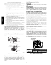
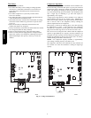
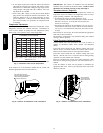
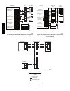
Communication and Status Function Lights
For Infinity Control only, Green communications (COMM)
Light
A green LED (COMM light) on the outdoor board (see Fig. 6)
indicates successful communication with the other system
products. The green LED will remain OFF until communication is
established. Once a valid command is received, the green LED will
turn ON continuously. If no communication is received within 2
minutes, the LED will be turned OFF until the next valid
communication.
Amber Status Light
An amber colored STATUS light is used to display the operation
mode and fault codes as specified in the troubleshooting section.
See Table 4 for codes and definitions.
NOTE: Only one code will be displayed on the outdoor unit
control board (the most recent, with the highest priority).
Crankcase Heater Operation
The crankcase heater is energized during off cycle below 65°F
(18.33°C).
Outdoor Fan Motor Operation
The outdoor unit control energizes outdoor fan anytime
compressor is operating, except for defrost or low--ambient
cooling. The outdoor fan remains energized if a pressure switch or
compressor overload should open. Outdoor fan motor will
continue to operate for one minute after the compressor shuts off
when the outdoor ambient is greater than or equal to 100°F
(37.78°C). This reduces pressure dif ferential f or easier starting on
next cycle.
The outdoor fan motor is a PSC type. A fan relay on the control
board turns the fan off and on by opening and closing a high
voltage circuit to the motor. It does not change speeds between low
and high stage operation.
25HPA6