


5
Install Liquid-- Line Filter Drier Indoor
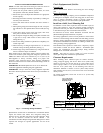
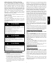
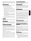
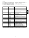
Refer to Fig. 3 and install filter drier as follows:
1. Braze 5--in. (127 mm) liquid tube to the indoor coil.
2. Wrap filter drier with damp cloth.
3. Braze filter drier to above 5--in. (127 mm) liquid tube. Flow
arrow must point towards indoor coil.
4. Connect and braze liquid refrigerant tube to the filter drier.
CAUTION
!
UNIT DAMAGE HAZARD
Failure to follow this caution may result in equipment damage
or improper operation.
Installation of filter drier in liquid line is required.
A05227
Fig. 3 -- Liquid--Line Filter Drier
Refrigerant Tubing connection Outdoor
Connect vapor tube to fitting on outdoor unit vapor service valves
(see T able 1).
Install Adapter Tube
1. Remove plastic retainer holding outdoor piston in liquid
service valve.
2. Check outdoor piston size with matching number listed on
unit rating plate.
3. Locate plastic bag taped to unit containing adapter tube.
4. Remove TeflonR washer from bag and install on open
end of liquid service valve.
5. Remove adapter tube from bag and connect threaded nut to
liquid service valve. Tighten nut finger tight and then with
wrench tighten an additional 1/2 turn (15 ft--lb).
DO NOT OVERTIGHTEN!
Sweat Connections
CAUTION
!
UNIT DAMAGE HAZARD
Failure to follow this caution may result in equipment
damage or improper operation.
S Use a brazing shield
S Wrap service valves with wet cloth or heat sink material.
Use refrigerant grade tubing. Service valves are closed from factory
and ready for brazing. After wrapping service valve with a wet
cloth, braze sweat connections using industry accepted methods
and materials. Consult local code requirements. Refrigerant tubing
and indoor coil are now ready for leak testing. This check should
include all field and factory joints.
Evacuate Refrigerant Tubing and Indoor Coil
CAUTION
!
UNIT DAMAGE HAZARD
Failure to follow this caution may result in equipment
damage or improper operation.
Never use the system compressor as a vacuum pump.
Refrigerant tubes and indoor coil should be evacuated using the
recommended deep vacuum method of 500 microns. The alternate
triple evacuation method may be used. See Service Manual for
triple evacuation method. Always break a vacuum with dry
nitrogen.
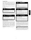
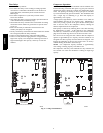
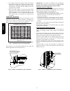
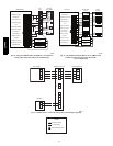
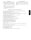
Deep Vacuum Method
The deep vacuum method requires a vacuum pump capable of
pulling a vacuum of 500 microns and a vacuum gauge capable of
accurately measuring this vacuum depth. The deep vacuum method
is the most positive way of assuring a system is free of air and
liquid water. (See Fig. 4)
500
MINUTES
01234567
1000
1500
LEAK IN
SYSTEM
VACUUM TIGHT
TOO WET
TIGHT
DRY SYSTEM
2000
MICRONS
2500
3000
3500
4000
4500
5000
A95424
A95424
Fig. 4 -- Deep Vacuum Graph
Final Tubing Check
IMPORTANT: Check to be certain factory tubing on both indoor
and outdoor unit has not shifted during shipment. Ensure tubes are
not rubbing against each other or a ny sheet metal. Pay close
attention t o feeder tubes, making sure wire ties on feeder tubes are
secure and tight.
Make Electrical Connections
!
WARNING
ELECTRICAL SHOCK HAZARD
Failure to follow this warning could result in personal
injury or death.
Do not supply power to unit with compressor terminal box
cover removed.
Be sure field wiring complies with local and national fire, safety,
and electrical codes, and voltage to system is within limits shown
on unit rating plate. Contact local power company for correction of
improper voltage. See unit rating plate for recommended circuit
protection device.
25HPA6