


8
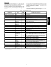
Time Delays
The unit time delays include:
S Five minute time delay to start cooling or heating operation
when there is a call from the thermostat or user interface. To
bypass this feature, momentarily short and release Forced
Defrost pins.
S Five minute compressor re--cycle delay on return from a
brown--out condition.
S Two minute time delay to return to standby operation from last
valid communication (with Infinity only).
S One minute time delay of outdoor fan at termination of cooling
mode when outdoor ambient is greater than or equal to 100_F
(37.78_C).
S Fifteen second delay at termination of defrost before the
auxiliary heat (W1) is de--energized.
S Twenty second delay at termination of defrost before the outdoor
fan is energized (unless fan delay defeated).
S Thirty second compressor delay when quiet shift enabled.
S There is no delay between staging from low to high and from
high to low capacity. The compressor will change from low to
high and from high to low capacity “on the fly” to meet the
demand.
Compressor Operation:
The basic scroll design has been modified with the addition of an
internal unloading mechanism that opens a by--pass port in the first
compression pocket, effectively reducing the displacement of the
scroll. The opening and closing of the by --pass port is controlled
by an internal electrically operated solenoid. The modulated scroll
uses a single step of unloading to go from full capacity to
approximately 67% capacity.
A single speed, high efficiency motor continues to run while the
scroll modulates between the two capacity steps. Modulation is
achieved by venting a portion of the gas in the first suction pocket
back to the low side of the compressor, thereby reducing the
effective displacement of the compressor .
Full capacity is achieved by blocking these vents, thus increasing
the displacement to 100%. A DC solenoid in the compressor
controlled by a rectified 24 volt AC signal in the external solenoid
plug moves the slider ring that covers and uncovers these vents.
The vent covers are arranged in such a manner that the compressor
operates at approximately 67% capacity when the solenoid is not
energized and 100% capacity when the solenoid is energized. The
loading and unloading of the two step scroll is done ”on the fly”
without shutting off the motor between steps.
NOTE: 67% compressor capacity translates to approximately
75% cooling or heating capacity at the indoor coil.
The compressor will always start unloaded and stay unloaded for
five seconds even when the thermostat is calling for high stage
capacity.
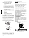
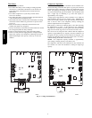
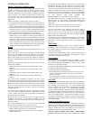
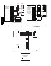
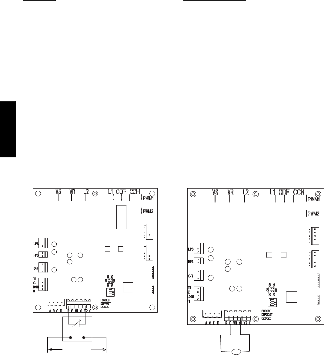
UTILITY RELAY
*
UTILITY SIGNAL
OPEN RELAY
* SUPPLIED BY UTILITY PROVIDER
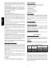
MODEL
PLUG
A06525
LLS
Liquid Line Solenoid
MODEL
PLUG
A06526
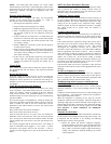
Fig. 6 -- 2 --Stage Control Board
25HPA6