


9
GENERAL INFORMATION
Infinity Controlled low ambient cooling:
This unit is capable of low ambient cooling down to 0°F (--17.8°C)
without a kit ONLY when using an Infinity Control. A low
ambient kit is not required for Infinity controlled low ambient
operation. The Infinity Control provides an automatic evaporator
freeze thermostat. Low ambient cooling must be enabled in the
User Interface setup. Fan may not begin to cycle until about 40°F
(4.4 °C) OAT. Fan will cycle based on coil and outdoor air
temperature.
Infinity controlled low ambient mode operates as follows:
S Fan is OFF when outdoor coil temperature is lessthan outdoorair
temperature (+ 3 _F/1.7_C) or outdoor fan has been ON for 30
minutes. (Fanisturnedofftoallowrefrigerantsystemtostabilize.)
S Fan is ON when outdoor coil temperature is less than outdoor air
temperature (+25_F/13.9_C) or outdoor coil temperature is more
than 80_F(26.7_C)orifoutdoorfanhasbeenOFF for30 minutes.
(Fan is turned on to allow refrigerant system to stabilize.)
S Low pressure switch is ignored for first 3 minutes during low
ambient start up. After 3 minutes, if LPS trips, then outdoor fan
motoristurnedofffor10 minutes,withthecompressorrunning. If
LPS closes within 10 minutes then cooling continues with the
outdoor fan cycling per the coil temperature routine listed above
for the remainder of the cooling cycle. If the LPS does not close
within 10 minutes, then the normal LPS trip response (shut down
cooling operation and generate LPS trip error) will occur.
Defrost
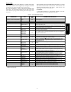
This control offers 5 possible defrost interval times: 30, 60, 90, 120
minutes, or AUTO.
Defrost intervals are selected by dip switches on the unit control
board or by the Infinity Control User Interface. The Infinity
Control selection overrides the control board dip switch settings.
Defrost interval times: 30, 60, 90, and 120 minutes or AUTO are
selected by the Infinity Control User Interface (the dip switches are
not used.)
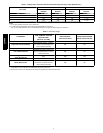
AUTO defrost adjusts the defrost interval time based on the last
defrost time as follows:
S When defrost time <3 minutes, the next defrost interval=120
minutes.
S When defrost time 3--5 minutes, the next defrost interval=90
minutes.
S When defrost time 5--7 minutes, the next defrost interval=60
minutes.
S When defrost time >7 minutes, the next defrost interval=30
minutes.
The control board accumulates compressor run time. As the
accumulated run time approaches the selected defrost interval time,
the control board monitors the coil temperature sensor for a defrost
demand. If a defrost demand exists, a defrost cycle will be initiated
at the end of the selected time interval. A defrost demand exists
when the coil temperature is at or below 32_F(0_C) for 4 minutes
during the interval.
The defrost cycle is terminated when the coil temperature reaches
65_F (18.33_C)or 10 minutes has passed. When OAT is > 25°F
(-- 3.9°C), defrost will occur in low or high stage as demanded by
the thermostat or User Interface.
If OAT is ≤25°F(3.9_C), defrost will occur in high stage only ,
regardless of thermostat or User Interface demand, and will
terminate at 50_F(10_C) coil temperature with a minimum of 2.5
minutes in defrost.
If the coil temperature does not reach 32_F(0_C) within the
interval, the interval timer will be reset and start over.
S Upon initial power up the first defrost interval is defaulted to 30
minutes. Remaining intervals are at selected times.
S Defrost is only allowed to occur below 50_F(10_C) outdoor
ambient temperature.
The outdoor fan output (ODF) will remain off for 20 seconds after
termination. This delay will allow time for the system to capture
the heat from the outdoor coil and reduce the “steam cloud” effect
that may occur on transition from defrost to heating cycle. The
outdoor fan output OFF delay of 20 seconds may be defeated to
enable the fan to ener gize immediately at the time of termination
and 12 seconds prior to the reversing valve de--energizing through
the User Interface setup screen (available with
SYSTXCCUID01 --C), or forced defrost pins as follows:
The ODF fan delay defeat can be toggled by shorting the forced
defrost pins for >15 seconds while in the standby mode (status
LED on solid). The LED will start to flash when the toggle has
taken place.
Status code 4 shows the fan delay defeat is active (no delay).
Status code 3 shows that it si not active (20 second delay).
The code will continue to be displayed until after the short is
removed. There is a 5 second wait before the code is cancelled
once the short is removed. the code that is flashing will finish
before going back to solid LED. The control is shipped with the
ODF fan delay defeat NOT active.
The change in status is remembered until toggled to a new status.
A power down/power up sequence will not reset the status. It may
be necessary to do the toggle twice to cycle to the desired state of
the defeat.
Defrost Hold
On a non--communicating system, if the thermostat becomes
satisfied (Y1 or Y1 and Y2) before the defrost cycle is terminated,
the control will “hold” in defrost mode and finish the defrost cycle
on the next call for heat.
On models with communicating Infinity Control, defrost hold is
not needed because the User Interface will complete the defrost
cycle before shutting down the system.
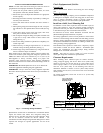
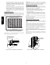
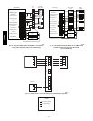
Forced Defrost
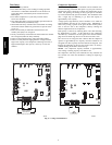
On a system with non--communicating (non--Infinity) control,
forced defrost can be initiated by manually shorting the 2--pin
header labeled FORCED DEFROST (see Fig 6) on the control
board for 5 seconds then releasing.
On a system with communicating (Infinity) control, forced defrost
is initiated with the User Interface.
On all models, during a Forced Defrost:
S If coil temperature is at defrost temperature of 32_F(0_C), and
outdoor air temperature is below 50_F(10_C), a full defrost
sequence will occur.
S If coil temperature or outdoor air temperature does not meet the
above requirements, an abbreviated 30 second defrost will occur.
Quiet Shift
Quiet Shift is a field--selectable defrost mode which may eliminate
occasional noise that could be heard at the start of the defrost cycle
and restarting of the heating cycle. On a non--communicating
system, this feature must be enabled by selecting the 3rd position
of the 3--position dip switch. For communicating (Infinity)
systems, it must be enabled at the User Interface. When activated,
the following sequence of operation will occur. Reversing valve
will energize and compressor will turn off for 30 seconds, then turn
back on to complete defrost. At the end of the defrost cycle, the
reversing valve de--energizes, compressor will turn off for another
30 seconds, and the fan will turn off for 40 seconds, before starting
in the heating mode.
Liquid--Line Solenoid Accessory
In heat pump long--line applications, a liquid --line solenoid is
required to control refrigerant migration in the heating mode. The
solenoid should be installed near the outdoor unit with the arrow
facing the outdoor unit. This is the direction of flow control. See
application manual for long--lin e application details.
Accessory Liquid Solenoid with Infinity Communicating
Control: When using the Infinity Control, the liquid --line solenoid
25HPA6