


2
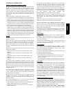
INSTALLATION RECOMMENDATIONS
NOTE: I n some cases noise in the living area has been traced to
gas pulsations from improper installation of equipment.
1. Locate unit away from windows, patios, decks, etc. where
unit operation sound may disturb customer.
2. Ensure that vapor and liquid tube diameters are appropriate
for unit capacity.
3. Run refrigerant tubes as directly as possible by avoiding un-
necessary turns and bends.
4. Leave some slack between structure and unit to absorb vi-
bration.
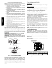
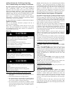
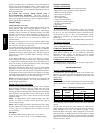
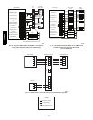
5. When passing refrigerant tubes through the wall, seal open-
ing with RTV or other pliable silicon--ba sed caulk. (See Fig.
1.)
6. Avoid direct tubing contact with water pipes, duct work,
floor joists, wall studs, floors, and walls.
7. Do not suspend refrigerant tubing from joists and studs with
a rigid wire or strap which comes in direct contact with
tubing.(See Fig. 1.)
8. Ensure that tubing insulation is pliable and completely sur-
rounds vapor tube.
9. When necessary, use hanger straps which are 1 in. wide and
conform to shape of tubing insulation. (See Fig. 1.)
10. Isolate hanger straps from insulation by using metal sleeves
bent to conform to shape of insulation.
When outdoor unit is connected to factory--approved indoor unit,
outdoor unit contains system refrigerant charge for operation with
AHRI rated indoor unit when connected by 15 ft. (4.57 m) of
field--supplied or factory accessory tubing. For proper unit
operation, check refrigerant charge using charging information
located on control box cover and/or in the Check Charge section of
this instruction.
IMPORTANT: Maximum liquid--line size is 3/8--in. OD for all
residential applications including long line applications.
IMPORTANT: Always install the factory--supplied liquid--line
filter drier. Obtain replacement filter driers from your distributor or
branch.
INSULATION
SUCTION TUBE
LIQUID TUBE
OUTDOOR WALL INDOOR WALL
LIQUID TUBE
SUCTION TUBE
INSULATION
CAULK
HANGER STRAP
(AROUND SUCTION
TUBE ONLY)
JOIST
1” (25.4 mm)
MIN
THROUGH THE WALL
SUSPENSION
A07588
Fig. 1 -- Connecting Tubing Installation
Specifications for this unit in residential new construction market
require the outdoor unit, indoor unit, refrigerant tubing sets,
metering device, and filter drier listed in presale literature. There
can be no deviation. Consult the Service Manual – Air
Conditioners and Heat Pumps Using Puron® Refrigerant to obtain
required unit changes for specific applications and for R --22
retrofit.
Check Equipment and Job Site
Unpack Unit
Move to final location. Remove carton taking care not to damage
unit.
Inspect Equipment
File claim with shipping company prior to installation if shipment
is damaged or incomplete. Locate unit rating plate on unit corner
panel. It contains information needed to properly install unit.
Check rating plate to be sure unit matches job specifications.
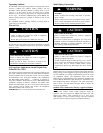
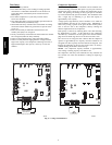
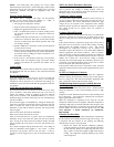
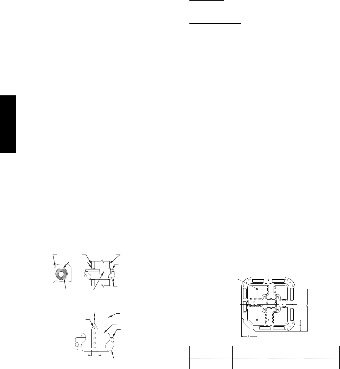
Install on a Solid, Level Mounting Pad
If conditions or local codes require the unit be attached to pad, tie
down bolts should be used and fastened through knockouts
provided in unit base p an. Refer to unit mounting pattern in Fig. 2
to determine base pan size and knockout hole location.
For hurricane tie downs, contact distributor for details and PE
(Professional Engineer)Certification, if required.
On rooftop applications, mount on level platform or frame. Place
unit above a load--bearing wall and isolate unit and tubing set from
structure. Arrange supporting members to adequately support unit
and minimize transmission of vibration to building. Consult local
codes governing rooftop applications.
Roof mounted units exposed to winds above 5 mph may require
wind baffles. Consult the Service Manual -- Residential Split
System Air Conditioners and Heat Pumps Using Puron®
Refrigerant for wind baffle construction.
NOTE: Unit must be level to within ±2° (±3/8 in./ft,±9.5
mm/m.)per compressor manufacturer specifications.
Clearance Requirements
When installing, allow sufficient space for airflow clearance,
wiring, refrigerant piping, and service. Allow 24 in. (609.6 mm)
clearance to service end of unit and 48 in. (1219.2 mm) (above
unit. For proper airflow, a 6 --in. (152.4 mm) clearance on 1 side of
unit and 12 --in. (304.8 mm) on all remaining sides must be
maintained. Maintain a distance of 24 in. (609.6 mm) between
units. Position so water, snow, or ice from roof or eaves cannot fall
directly on unit.
On rooftop applications, locate unit at least 6 in. (152.4 mm)
above roof surface.
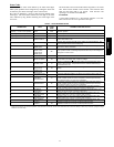
3/8---in.(9.53 mm)Dia.
Tiedown Knockouts in
Basepan(2)Places
View From Top
UNIT BASE PAN
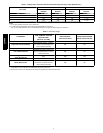
Dimension in. (mm)
TIEDOWN KNOCKOUT LOCATIONS in. (mm)
A B C
35 X 35
(889 X 889)
9–1/8 (231.8) 6–9/16 (166.7) 28–7/16 (722.3)
A05177
Fig. 2 -- Tiedown Knockout Locations
25HPA6