


13
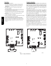
Status Codes
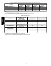
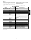
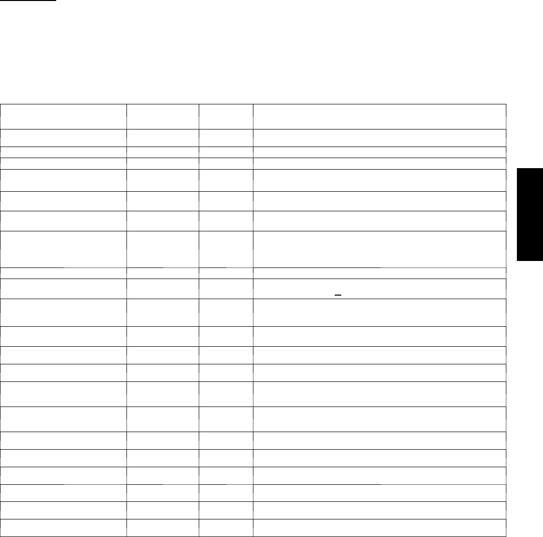
Table 4 shows the status codes flashed by the amber status light.
Most system problems can be diagnosed by reading the status code
as flashed by the amber status light on the control board.
The codes are flashed by a series of short and long flashes of the
status light. The short flashes indicate the first digit in the status
code, followed by long flashes indicating the second digit of the
error code.
The short flash is 0.25 seconds ON and the long flash is 1.0 second
ON. Time between flashes is 0.25 seconds. Time between short
flash and first long flash is 1.0 second. Time between code
repeating is 2.5 seconds with LED OFF.
EXAMPLE:
3 short flashes followed by 2 long flashes indicates a 32 code.
Table 4 shows this to be low pressure switch open.
Table 4 – TROUBLESHOOTING
OPERATION
FAULT
AMBER LED
FLASH
CODE
POSSIBLE CAUSE AND ACTION
Standby – no call for unit operation None
On solid, no
flash
Normal operation
Low Stage Cool/Heat Operation None 1, pause Normal operation
High Stage Cool/Heat Operation None 2, pause Normal operation
System Commu-
nications Failure
16 Communication with User Interface lost. Check wi ring t o User Interface,
indoor and outdoor units
Invalid Model Plug 25
Control does not detect a model plug or detects an invalid model plug. Unit
will not operate without correct model plug.
High Pressure
Switch Open
31*
High---pressure switch trip. Check refrigerant charge, outdoor fan operation
and coils for airflow restrictions.
Low Pressure
Switch or Dis-
charge Temp
Switch Open
32*
Low--- pressure switch or discharge temperature switch trip. Check refrigerant
charge an d indoor air flow.
Control Fault 45 Outdoor unit control board has failed. Control board needs to be replaced.
Brown Out (230 v) 46
Line voltage < 187v f or at least 4 seconds. Compressor and fan operation
not allowed until voltage>
190v. Verify line voltage.
No 230v at Unit 47
There is no 230v at the contactor when indoor unit is powered and cooling/
heating demand exists. Verify the disconnect is closed and 230v wiring is
connected to the unit.
Outdoor Air Temp
Sensor Fault
53
Outdoor air sensor not reading or out of range. Ohm out sensor and check
wiring.
Outdoor C oil
Sensor Fault
55 Coil sensor not readingor out of range. Ohm out sensor and check wiring.
Thermistors ou t of
range
56
Improper relationship between coil sensor and ou tdoor air sensor. Ohm out
sensors and check wiring.
Low Stage
Thermal Cutout
71*
Compressor operation detected then disappears while low stage demand
exists. Possible causes are internal compressor overload trip or start relay
and capacitor held in circuit too long (if installed).
High Stage
Thermal Cutout
72*
Compressor operation detected then disappears while high stage demand
exists. Possible causes are internal compressor overload trip or start relay
and capacitor held in circuit too long (if installed).
Contactor Shorted 73
Compressor voltage sensed when no demand for compressor operation
exists. Contactor may be s tuck closed or there is a wiring error.
No 230V a t
Compressor
74
Compressor voltage not sensed when compressor should be starting. Con-
tactor may be stuck open or there is a wiring error.
Low Stage
Thermal Lockout
81
Thermal cutout occurs in three consecutive low/high stage cycles. Low
stage locked out for 4 hours or until 24v power recycled.
High Stage
Thermal Lockout
82
Thermal cutout occurs in three consecutive high/low stage cycles. High
stage locked out for 4 hours or until 24v power recycled.
Low --- Pressure
Lockout
83
Low pressure switch trip has occurred during 3 c onsecutive cycles. Unit
operation locked out for 4 hours or until 24v power recycled.
High--- Pressure
Lockout
84
High pressure switch trip has occurred during 3 consecutive cycles. Unit
operation locked out for 4 hours or until 24v power recycled.
* Sequence: Compressor contactor is de---energized and outdoor fan isenergizedfor up to 15 minutes. If demand stillexists, control will energize compressor contactorafter 15 minute
delay.If faultis cleared, unitwill resume operation. If faultstill exists, fan shutsoff, and error codecontinuesto flash. Control will attemptre---start every 15 minutes. Cycling low voltage
defeats the 15 m inute delay .
25HPA6