


12
2. If the expected result is not achieved, remove the solenoid
plug from the compressor and with the unit running and the
User Interface or thermostat calling for high stage, test the
voltage output at the plug with a DC voltmeter. The read-
ing should be 24 volts DC.
3. If the correct DC voltage is at the control circuit molded
plug, measure the compressor unloader coil resistance. The
resistance should be 32 to 60 ohms depending on com-
pressor temperature. If the coil resistance is infinity, much
lower than 32 ohms, or is grounded, the compressor must
be replaced.
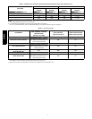
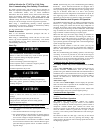
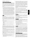
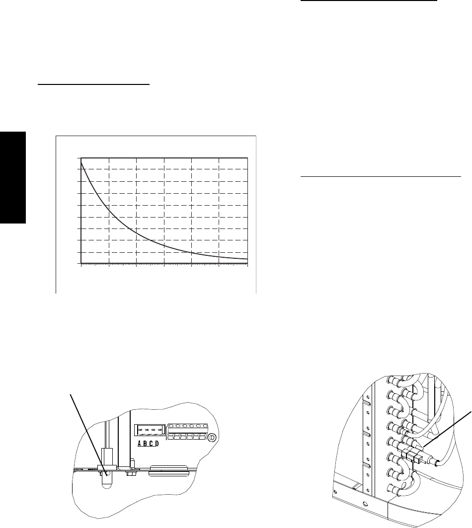
Temperature Thermistors
Thermistors are electronic devices which sense temperature. As the
temperature increases, the resistance decreases. Thermistors are
used to sense outdoor air (OAT) and coil temperature (OCT).
Refer to Fig. 7 for resistance values versus temperature.
0
10
20
30
40
50
60
70
80
90
0
(-17.77)
20
(-6.67)
40
(4.44)
60
(15.56)
80
(26.67)
100
(37.78)
120
(48.89)
TEMPERATURE °F (°C)
RESISTANCE (KOHMS)
THERMISTOR CURVE
A08054
Fig. 7 -- Resistance Values Versus Temperature
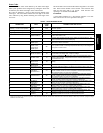
If the outdoor air or coil thermistor should fail, the control will
flash the appropriate fault code. (See Table 4.)
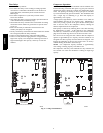
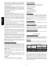
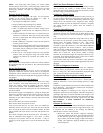
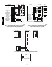
IMPORTANT: The outdoor air thermistor and coil thermistor
should be factory mounted in the final locations. Check to ensure
thermistors are mounted properly per Fig. 8 and Fig. 9.
Thermistor Sensor Comparison
The control continuously monitors and compares the outdoor air
temperature sensor and outdoor coil temperature sensor to ensure
proper operating conditions. The comparison is:
S In cooling if the outdoor air sensor indicates ≥ 10_F
(≥ 5.6_C) warmer than the coil sensor (or) the outdoor air sensor
indicates ≥ 20_F(≥ 11_C) cooler than the coil sensor, the
sensors are out of range.
S In heating if the outdoor air sensor indicates ≥ 35_F(≥ 19.4_C)
warmer than the coil sensor (or) the outdoor air sensor indicates
≥ 10_F(≥ 5.6_C) cooler than the coil sensor, the sensors are out
of range.
If the sensors are out of range, the control will flash the appropriate
fault code as shown in Table 4.
The thermistor comparison is not performed during low ambient
cooling or defrost operation.
Failed Thermistor Default Operation
Factory defaults have been provided in the event of failure of
outdoor air thermistor (OAT) and/or outdoor coil thermistor
(OCT).
If the OAT sensor should fail, low ambient cooling will not be
allowed and the one--minute outdoor fan off delay will not occur.
Defrost will be initiated based on coil temperature and time.
If the OCT sensor should fail, low ambient cooling will not be
allowed. Defrost will occur at each time interval during heating
operation, but will terminate after 5 minutes.
If there is a thermistor out of range error, defrost will occur at each
time interval during heating operation, but will terminate after 5
minutes.
Count the number of short and long flashes to determine the
appropriate flash code. Table 4 gives possible causes and actions
related to each error.
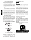
OAT Thermistor must be
locked in place with spherical
nib end facing towards the
front of the control box
Fig. 8 -- Outdoor Air Thermistor (OAT) Attachment
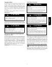
OCT Thermistor
must be secured
tight on stub tube.
Fig. 9 -- Outdoor Coil Thermistor (OCT) Attachment
25HPA6