


6
NOTE: Operation of unit on improper line voltage constitutes
abuse and could affect unit reliability . See unit rating plate. Do not
install unit in system where voltage may fluctuate above or below
permissible limits.
NOTE: Use copper wire only between disconnect switch and unit.
NOTE: Install branch circuit disconnect of adequate size per NEC
to handle unit starting current. Locate disconnect within sight from
and readily accessible from unit, per Section 440--14 of NEC.
Route Ground and Power Wires
Remove access panel to gain access to unit wiring. Extend wires
from disconnect through power wiring hole provided and into unit
control box.
!
WARNING
ELECTRICAL SHOCK HAZARD
Failure to follow this warning could result in personal
injury or death.
The unit cabinet must have an uninterrupted or unbroken
ground to minimize personal injury if an electrical fault
should occur. The ground may consist of electrical wire or
metal conduit when installed in accordance with existing
electrical codes.
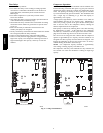
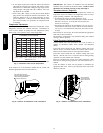
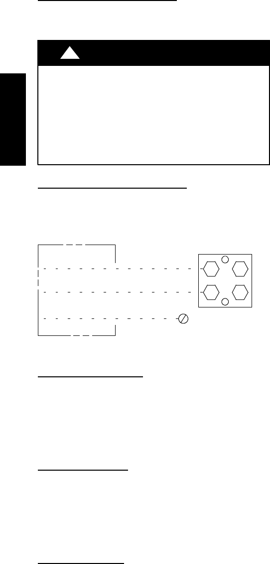
Connec t Ground and Power Wires
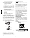
Connect ground wire to ground connection in control box for
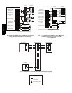
safety. Connect power wiring to contactor as shown in Fig. 5.
DISCONNECT
PER N. E. C.AND/OR
LOCAL CODES
CONTACTOR
GROUND
LUG
FIELD GROUND
WIRING
FIELD POWER
WIRING
A91056
Fig. 5 -- Line Power Connections
Connect Control Wiring
Route low voltage control wires through control wiring grommet
and connect leads to control board.
Connect to Infinity connections ABCD only when Infinity User
Interface is available.
Standard non --communicating thermostat connections are possible
when you connect to standard thermostat connections R, C, W, Y1,
Y2, and O. Refer to wiring label for further clarification.
General Information
Use No. 18 AWG color-- coded, insulated (35°C minimum) wire for
all installations.
All wiring must be NEC Class 1 and must be separated from
incoming power leads.
Use furnace transformer, fan coil transformer, or accessory
transformer for control power, 24v/40va minimum. The outdoor
unit requires a minimum of 27va/24vac control power.
Final Wiring Check
IMPORTANT: Check factory wiring and field wire connections
to ensure terminations are s ecured properly. Check wire routing to
ensure wires are not in contact with tubing, sheet metal, etc.
CompressorCrankcaseHeater
Furnish power to crankcase heater a minimum of 24 hr before
starting unit. To furnish power to heater only, set thermostat to
OFF and close electrical disconnect to outdoor unit.
Airflow Selections (ECM F urnaces)
The ECM Furnaces provide blower operation to match the
capacities of the compressor during high and low stage cooling
operation. Tap selections on the furnace control board enable the
installing technician to select the proper airflows for each stage of
cooling. Below is a brief summary of the furnace airflow
configurations
1. The Y2 call for high stage cooling energizes the “Cool” tap
on the control board. The grey wire from cool tap is connec-
ted to tap 5 on the motor. Refer to the furnace Product Data
to find the corresponding airflow. If the airflow setting for
high cooling needs to be switched from tap 5 to a different
tap, jumper a connection from the cool tap to the desired tap
so that the Y2 signal is communicated via the cool tap to the
desired speed tap.
2. The Y1 call for low stage cooling energizes the “Fan” tap
on the control board. The red wire from the fan tap is con-
nected to tap 1 on the motor. Refer to the furnace Product
Data to find the corresponding airflow. If the airflow setting
for low cooling needs to be switched from tap 1 to a differ-
ent tap, jumper a connection from the Fan tap to the desired
tap so that the Y1 signal is communicated via the Fan tap to
the desired speed tap. The Y1 setting will also govern the
continuous fan airflow for the furnace.
Refer to the furnace literature for further details.
Airflow Selection for Variable Speed Furnaces
(non--communicating)
The variable speed furnaces provide blower operation to match the
capacities of the compressor during high and low stage cooling
operation. The furnace control board allows the installing
technician to select the proper airflows for each stage of cooling.
Below is a summary of required adjustments. See furnace
installation instructions for more details:
1. Turn SW1----5 ON for 400 CFM/ton airflow or OFF for 350
CFM/ton airflow. Factory default is OFF.
2. The A/C DIP switch setting determines airflow during high
stage cooling operation. Select the A/C DIP switch setting
corresponding to the available airflow shown in the furnace
Installation Instructions that most closely matches the re-
quired airflow shown in the air conditioning Product Data
for HIGH speed.
3. The CF DIP switch setting determines airflow during low
stage c ooling operation. Select the CF DIP switch setting
corresponding to the available airflow shown in the furnace
installation instructions that most closely matches the re-
quired airflow shown in the air conditioning Product Data
for LOW speed. If a higher or lower continuous fan speed is
desired, the continuous fan speed can be changed using the
fan switch on the thermostat. Refer to the furnace Installa-
tion Instructions for details of how to use this feature.
25HPA6