


11
NOTE: The model plug takes priority over factory model
information input at the factory. If the model plug is removed after
initial power up, the unit will operate according to the last valid
model plug installed, and flash the appropriate fault code
temporarily.
Pressure Switch Protection
The outdoor unit is equipped with high-- and low--pressure
switches. If the control senses the opening of a high-- or
low--pressure switch, it will respond as follows:
1. De--energize the compressor contactor.
2. Keep the outdoor fan operating for 15 minutes.
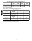
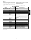
3. Display the appropriate fault code (see Table 4).
4. After a 15 minute delay, if there is a call for cooling or heat-
ing and LPS or HPS is reset, the compressor contactor is
energized.
5. If LPS or HPS has not closed after a 15 minute delay, the
outdoor fan is turned off. If the open switch closes anytime
after the 15 minute delay, then resume operation with a call
for cooling or heating.
6. If LPS or HPS trips 3 consecutive cycles, the unit operation
is locked out for 4 hours.
7. In the event of a high--pressure switch trip or high--pressure
lockout, check the refrigerant charge, outdoor fan operation,
and outdoor coil (in cooling) for airflow restrictions, or in-
door airflow in heating.
8. In the event of a low--pressure switch trip or low--pressure
lockout, check the refrigerant charge and indoor airflow
(cooling) and outdoor fan operation and outdoor coil in
heating.
Control Fault
If the outdoor unit control board has failed, the control will flash
the appropriate fault code (see Table 4). The control board should
be replaced.
Brown--Out Protection
If the line voltage is less than 187v for at least 4 seconds, the
appropriate compressor contactor and fan relay are de--energized.
Compressor and fan operation are not allowed until voltage is a
minimum of 190v. The control will flash the appropriate fault code
(see T able 4).
2230V Brown--Out Protection Defeated
The brownout feature can be defeated if needed for severe noisy
power conditions. This defeat should always be a last resort to
solving the problem. Defeat is available on the User Interface
setup screen (available with SYSTXCCUID01--C ), or can be
initiated through the forced defrost pins for non--communicating
systems as follows:
The brownout toggle is accomplished by s orting the defrost pins
from power up with the OAT and OCT sensor connector removed.
After 3 seconds, the status of the force defrost short and the
OAT/OCT as open will be checked. If correct, then the brownout
will be toggled.
Status code 6 shows the brownout is disabled.
Status code 5 shows the brownout is active.
After the brownout defeat is set, power down and reinstall the
OAT/OCT sensor and remove the short from the forced defrost
pins. As long as the short on the forced defrost remains, the OAT
and OCT faults will not be cleared. The code will continue to be
flashed.
The control is shipped with the brownout active. The change in
status is remembered until toggled to a new status. A power
down/power up sequence will not reset the status. it may be
necessary to do the toggle twice to cycle to the desired state of the
defeat.
230V Line (Power Disconnect) Detection
If there is no 230v at the compressor contactor(s) when the indoor
unit is powered and cooling or heating demand exists, the
appropriate fault code is displayed. Verify the disconnect is closed
and 230v wiring is connected to the unit.
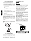
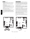
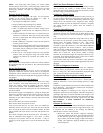
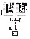
Compressor Voltage Sensing
The control board input terminals labeled VS and L2 (see Fig. 6)
are used to detect compressor voltage status and alert the user of
potential problems. The control continuously monitors the high
voltage on the run capacitor of the compressor motor. Voltage
should be present any time the compressor contactor is energized
and voltage should not be present when the contactor is
de--energized.
Contactor Shorted Detection
If there is compressor voltage sensed when there is no demand for
compressor operation, the contactor may be stuck closed or there
may be a wiring error. The control will flash the appropriate fault
code.
If the control senses the compressor voltage after start--up and is
then absent for 10 consecutive seconds while cooling or heating
demand exists, the thermal protector is open. The control
de--energizes the compressor contactor for 15 minutes, but
continues to operate the outdoor fan. The control Status LED will
flash the appropriate code shown in Table 4. After 15 minutes,
with a call for low or high stage cooling or heating, the compressor
contactor is energized. If the thermal protector has not re--set, the
outdoor fan is turned off. If the call for cooling or heating
continues, the control will energize the compressor contactor every
15 minutes. If the thermal protector closes, (at the next 15 minute
interval check) the unit will resume operation.
If the thermal cutout trips for three consecutive cycles, then unit
operation is locked out for 4 hours and the appropriate fault code is
displayed.
No 230V at Compressor Contactor
If the compressor voltage is not sensed when the compressor
should be starting, the appropriate contactor may be stuck open or
there is a wiring error. The control will flash the appropriate fault
code. Check the contactor and control box wiring.
Troubleshooting units for p r oper switching between
low & high
stages
Check the suction pressures at the service valves. Suction pressure
should be reduced by 3--10% when switching from low to high
capacity.
Compressor current should increase 20 --45% when switching from
low to high stage. The compressor solenoid when energized in
high stage, should measure 24vac.
When the compressor is operating in low stage the 24v DC
compressor solenoid coil is de--energized. When the compressor is
operating in high stage, the 24v DC solenoid coil is energized. The
solenoid plug harness that is connected to the compressor HAS an
internal rectifier that converts the 24v DC signal to 24v AC. DO
NOT INSTALL A PLUG WITHOUT AN INTERNAL
RECTIFIER.
Unloader Test Procedure
The unloader is the compressor internal mechanism, controlled by
the DC solenoid, that modulates between high and low stage. If it
is suspected that the unloader is not working, the following
methods may be used to verify operation.
1. Operate the system and measure compressor amperage.
Cycle the unloader on and off at 30 second plus intervals at
the User Interface (from low to high stage a nd back to low
stage). Wait 5 seconds after staging to high before taking a
reading. The compressor amperage should go up or down
at least 20 percent.
25HPA6