


Installation & User Manual
June 2013 Ed 19UK
Page 17 of 28
Installation
Prior to installation please check that:
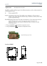
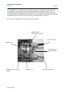
• the serial numbers on the transducer, amplifier and lid of amplifier box agree. The serial
numbers are to be found on the inside of the lid of the amplifier box on the bottom line -
amplifier S/N and transducer S/N on the range label.
• the transducer is fitted in the correct tank.
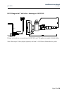
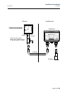
• the transducer is correctly connected to the amplifier.
NOTE: The white and brown wires in the transducer cable are only used when a Pt100 sensor
is built into the transducer.
• all cable glands are properly secured to the amplifier box. Use torque of 6 Nm.
• the amplifier box is mounted in such a way that the breather tube cannot be flooded.
• the cable is fastened with cable clips with a distance of max. 50 cm.
• the cable isolation is not damaged (cracks, weld spatter, burns etc.).
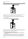
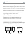
• shut-off valves can be either ball valves or other valves not generating over pressure exceeding
4 x the transducer range between valve seat and transducer when the valve is closed.
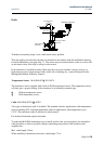
As for flange mounted applications it is recommended that a ball valve is fitted in the front of the
transducer to facilitate testing and calibrating of the transmitter.
Using a shielded cable to the 4-20 mA signal, the shield should not be connected in the amplifier
box but the earth terminal of the instrument. Using a shielded cable ensures maximum protection
against electric noise.