


Installation & User Manual
Ed 19UK June 2013
Page 2 of 28
Table of contents
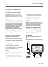
Description and Operation ............................................................................................. 3
MAS2600 Tank Contents Transmitter ..............................................................................................3
Application .........................................................................................................................................3
Intrinsically Safe in Hazardous Areas ...............................................................................................3
Type Approvals .................................................................................................................................3
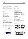
Technical Specifications ................................................................................................ 4
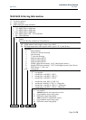
MAS2600 Ordering Information ................................................................................. 5
Type ...................................................................................................................................................6
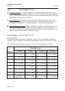
Measuring Ranges .............................................................................................................................6
Selecting the Measuring Range .....................................................................................................7
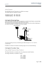
Selecting the Transducer Type ......................................................................................................7
Absolute Transducers ....................................................................................................................8
Basic Rules ....................................................................................................................................8
Forepeak Tank ...............................................................................................................................8
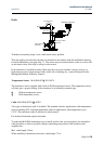
Draft ...............................................................................................................................................9
Temperature Sensor ...........................................................................................................................9
Cable ..................................................................................................................................................9
Brackets for Internal Mounting - drawing no. G022P010 ......................................................... 10
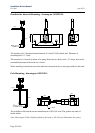
Pole Mounting - drawing no. G022P011 ................................................................................... 10
1” Pipe End Mounting - drawing no. G022P015 ....................................................................... 11
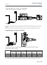
Flange Mounting - drawing no. G022P013 ................................................................................ 11
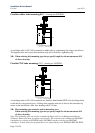
Flexible rubber tube mounting 80 .............................................................................................. 12
Flexible PTFE tube mounting .................................................................................................... 12
DN25 flange with 1” ball valve – drawing no. G022P019 ........................................................ 13
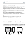
Amplifier Box ................................................................................................................................. 14
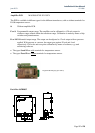
Deck Box 165B9035 .................................................................................................... 15
Handling ....................................................................................................................... 16
Installation .................................................................................................................... 17
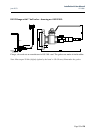
Intrinsically Safe Installation ....................................................................................... 19
Testing and Recalibrating ............................................................................................ 22
Testing ............................................................................................................................................. 22
Recalibrating Gauge Transmitter using Test Cup type G022S100 ................................................ 22
Recalibrating Gauge Transmitter using Vacuum (for gauge transmitters only) ............................ 23
Recalibrating the Absolute Transmitter using Test Cup type G022S100 ...................................... 24
Maintenance and Trouble Shooting ............................................................................. 26
Maintenance .................................................................................................................................... 26
Trouble Shooting ............................................................................................................................ 26
MAS2600 Test sheet ...................................................................................................................... 27