


Installation & User Manual
June 2013 Ed 19UK
Page 27 of 28
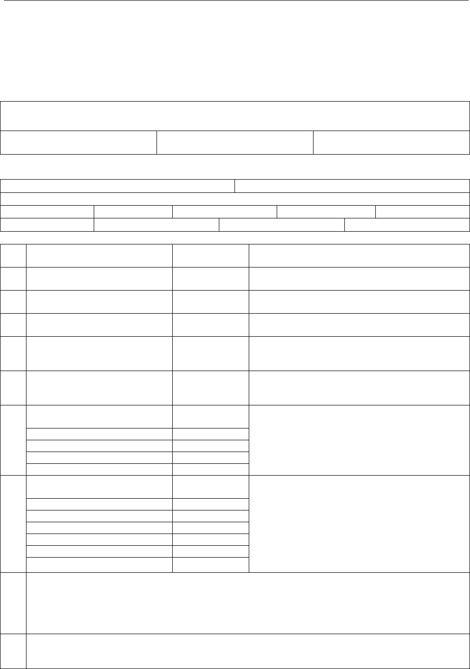
MAS2600 Test sheet
ATT.: Emerson Process Management
Marine Solutions
Damcos A/S, Service Department
FAX.: +45 5578 7272
Name:
Ship name:
Yard:
NB No:
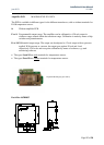
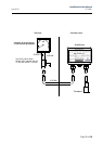
MAS2600:
Transducer serial no.:
Amplifier serial no.:
Tank name:
Liquid in tank
HFO:
DO:
Ballast:
Other:
The tank is
Full:
Empty:
Other:
Measurements:
1
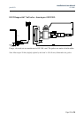
Measure voltage between terminal
5 and 6
V DC
Voltage should be in the range 14 to 33 V DC.
Check power supply.
2
Measure ripple voltage between
terminal 5 and 6
V AC
Voltage must not exceed 2 V AC. Check power
supply.
3
Measure sensor excitation voltage
between terminal 7 and 10
V DC Voltage should be in the range 3.0 to 6.2 V DC
4
Measure sensor excitation voltage
between terminal 8 and 9
mV DC Voltage should be in the range -15 to 100 mV DC
5
Measure current in supply lead to
terminal 5 mA DC
Current should be in the range 4 to 20 mA and the
same value as measured in point 6. If not the
amplifier may be defect.
6
Measure current in supply lead to
terminal 6 mA DC
Current should be in the range 4 to 20 mA and the
same value as measured in point 5. If not the
amplifier may be defect.
7
Measure sensor resistance with
sensor cable unconnected
If the resistance measured is less that 1 M Ohm the
sensor is defect.
Terminal 7 to cable shield
M Ohm
Terminal 8 to cable shield
M Ohm
Terminal 9 to cable shield
M Ohm
Terminal 10 to cable shield
M Ohm
8
Measure sensor bridge resistance
with sensor cable unconnected
If the resistance measured is less than 1 K Ohm or
greater that 50 K Ohm the sensor is defect.
Terminal 7 to Terminal 8
K Ohm
Terminal 7 to Terminal 9
K Ohm
Terminal 7 to Terminal 10
K Ohm
Terminal 8 to Terminal 9
K Ohm
Terminal 8 to Terminal 10
K Ohm
Terminal 9 to Terminal 10
K Ohm
9
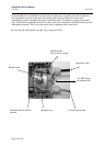
Visual inspection of the transmitter:
Is the cable damaged?
Are there sharp bends on the cable?
Are there moisture/liquids in the breather tube?
Is the diaphragm damaged?
10
Comments: