


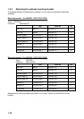
1-10
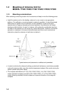
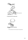
1.2.3 Mounting antenna unit of MODEL 1732/1732C/1733C
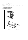
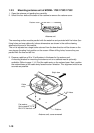
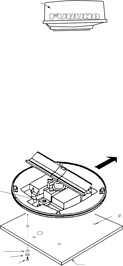
1. Open the antenna unit packing box carefully.
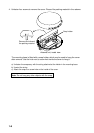
2. Unbolt the four bolts at the base of the radome to remove the radome cover.
Radome cover
Antenna unit
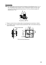
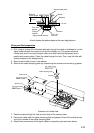
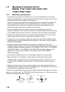
The mounting surface must be parallel with the waterline and provided with five holes (four
fixing holes and one cable ently) whose dimensions are shown in the outline drawing
attached at the end of this manual.
The unit is adjusted so a target echo returned from the bow direction will be shown on the
zero degree (heading line) position on the screen. When drilling holes, be sure they are
parallel with the fore and aft line.
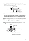
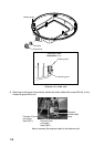
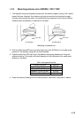
3. Prepare a platform of 5 to 10 millimeters in thickness for the antenna unit.
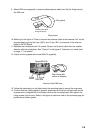
A mounting bracket for mounting the antenna unit on a sailboat mast is optionally
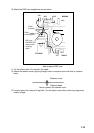
available. (Refer to page 1-14.) Find the cable entry on the radome base. Next, position
the radome base so the cable entry faces the stern direction. This alignment must be as
accurate as possible.
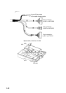
Flat washer
Spring washer
M10 x 25 Hex bolt
Platform
4- 12 Holes
Cable
entry
Ship's bow
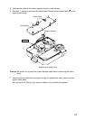
Antenna unit, cover removed