


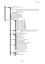
4. INSTALLATION
35
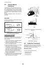
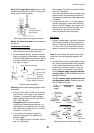
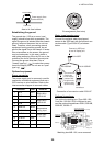
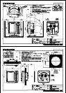
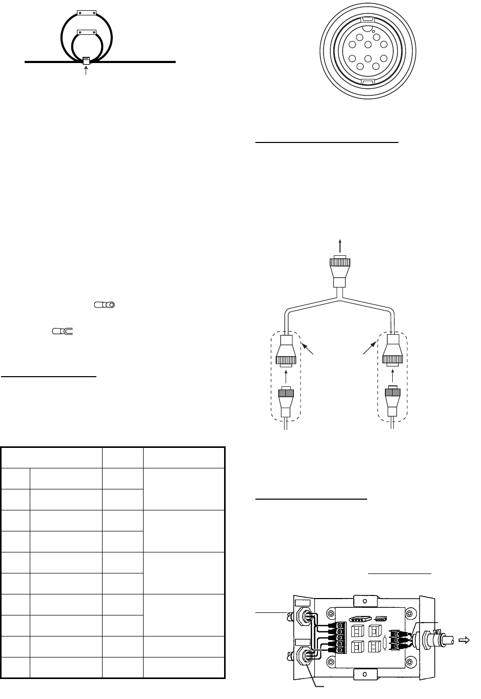
How to fix fuse holders
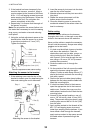
Establishing the ground
The ground wire (1.25 sq or more, local
supply) should be as short as possible. The
signal line ground is isolated from the chassis
ground, however the power line is not insu-
lated. Therefore, when connecting eternal
equipment having positive ground, do not
ground the signal line to the chassis. If exces-
sive noise shows on the screen, the ground
may be inadequate. In this case, attach a
steel plate measuring 20 cm by 30 cm on the
outside of the hull to provide a ground point.
Connect the ground wire there. Use a
"closed" type lug ( ) to make the connec-
tion at the display unit. Do not use an "open"
type lug ( ).
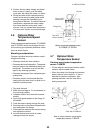
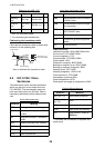
Optional equipment
Power connector
The power supply port is commonly used for
connection of external equipment such as a
GPS receiver or wind indicator. Refer to the
interconnection diagram to connect cables.
Pin assignment (front view)
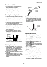
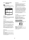
Water temp/speed sensor
Connect the optional water temp/speed
sensor to the XDR port with the optional con-
version cable (Type 02S4147) as shown
below.
Connection of conversion cable 02S4147
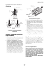
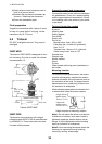
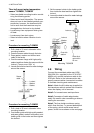
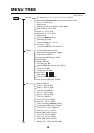
Optional transducer
The optional matching box (Type: MB-1100,
Code No.: 000-041-353) is required to con-
nect the optional transducers 50B-6, 50B-6B,
200B-5S, 50/200-1T.
Matching box MB-1100, cover removed
Connector Color Remarks
1TD-A WHT
IEC61162-1/
NMEA0183
2TD-B BLU
3 RD-A YEL
IEC61162-1/
NMEA0183
4RD-B GRN
5 TEMP-IN BRN
Temperature
analog input
6TEMP-IN-0V ORG
7 DC-P-IN RED
Power input
12-24 VDC
8 DC-N-IN BLK
9NC -
10 SHIELD -
Power supply line
s
(red and black)
Fuse holder
Cable tie
1
2
3
4
5
6
7
8
9
10
Tape connectors with
vulcanizing tape
and then vinyl tape
to waterproof them.
Bind tape ends with
cable ties to prevent
tape from unraveling.
Connect to XDR port
at rear of display unit
MJ-A10SPF
MJ-A10SRMD
MJ-A6SRMD
From
transducer
From
sensor
Connect 10P
connector to
XDR port on
rear of
display unit.
Green
(shield)
T
ransducer
50B-6/6B
2
00B-5S
50kHz
200kHz
SHIELD
BLK
RED
TB2
1
2
3
4
5
J2 J1
WHT
3
2
1
BLK
TB1
02P6348
Detach grommet;
attach cord lock.
Jumper block setting
J2: No output reduction (default)
J1: Output reduction
BLK
RED