


4-5
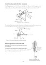
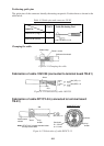
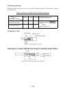
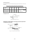
Positioning guide pins
The guide pins of the connector identify the mating receptacle. Position them as shown in the
table below.
Table 4-1 Connectors CN-A1, CN-A5, J201 and guide pins
Connector
Guide Pin
CN-A1 CN-A5 J201 Guide Pin Setting Tool
Guide Pin A (Large) 1 5 1
Type 10-910-0179-0
Guide Pin B (Small) 1 1 1
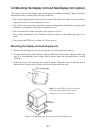
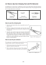
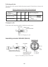
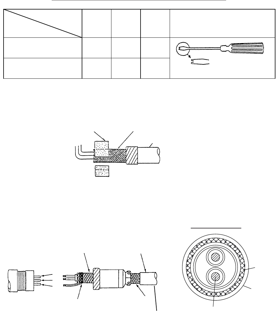
Clamping the cable
Fix the cable in the clamp where shield is folded back onto the armor.
Cable clamp
Shield + armor
Anticorrosive sheath
Figure 4-6 Clamping the cable
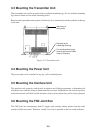
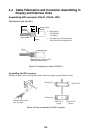
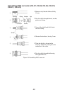
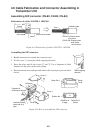
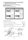
Assembling connector NCS-253P (CN-A15)
Armor Vinyl sheath
Taping
Solder lead wire to armor and
connect it to #1 pin of connector.
#2
#3
#1
Conductor
S = 1.25 mm
∅ = 1.35 mm
2
Vinyl
sheath
Armor
Cable DPYCY-1.25
Use cable DPYCY-1.25
(Japan standard cable)
or equivalent cable.
Figure 4-7 Assembling connector NCS-253P