


4-13
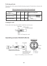
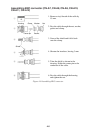
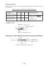
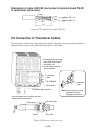
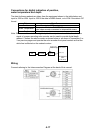
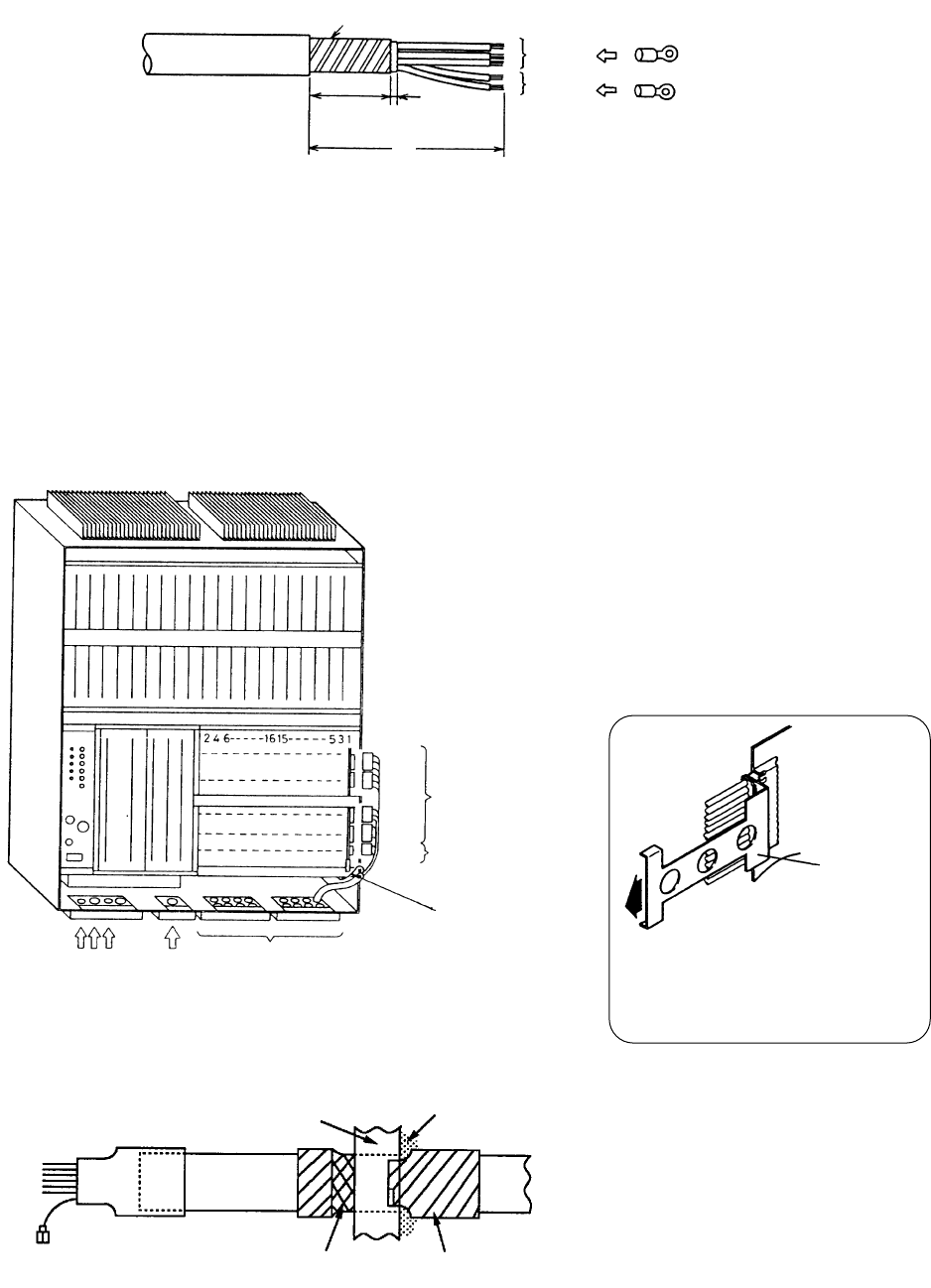
Fabrication of cable 10S1259 (connected to terminal board TB-D2
in raise/lower control box)
Armor
70
30 5
3.5sq
x 3
1.25sq
x 2
M4 (YEL) x 3
M4 (RED) x
2
Figure 4-22 Fabrication of cable 10S1259
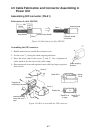
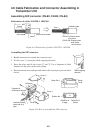
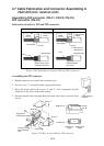
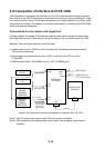
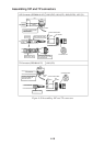
4.8 Connection of Transducer Cables
The transducer cables come with connectors attached. Plug the connectors into the proper re-
ceptacles on the receiver unit, referring to the labels on the cables.
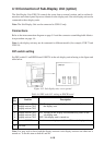
Transducer
cable
TD COMMON
Ground wire
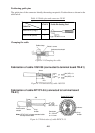
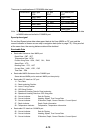
1. Connect transducer cables
to the XRS terminal board
referring to labels inside
the receiver unit.
2. Connect ground wires to
slip-on terminals.
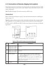
Transducer cable entrance
CN-C3
CN-C2
CN-C1
CN-C4
P1
P2
P3
P4
P5
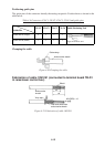
Cable clamp
Sleeve
Vinyl tape
Seal with putty.
Lead the cables into the receiver unit and
clamp them as shown below.
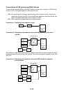
Connector
Puller
Note: Use the connector puller
(supplied) whenever
unplugging connectors.
Figure 4-23 Receiver unit, rear view