


4-10
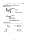
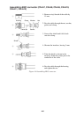
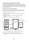
Positioning guide pins
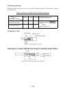
Guide pins of the connector are used to identify the mating receptacle. Position them as shown
the table below.
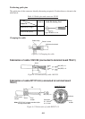
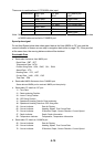
Table 4-3 Connectors CN-B2, CN-B3, CN-B4 and guide pins
Connector
Guide Pin
CN-B2 CN-B3 CN-B4 Guide Pin Setting Tool
Guide Pin A (Large) 1 1 3
Type 10-910-0179-0
Guide Pin B (Small) 1 1 1
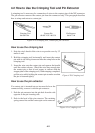
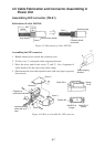
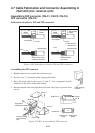
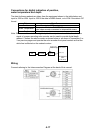
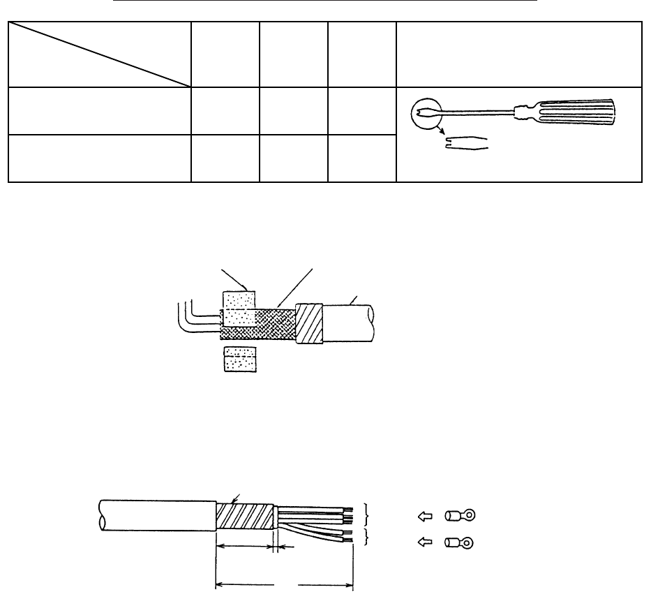
Clamping the cable
Cable clamp
Shield + armor
Anticorrosive sheath
Figure 4-16 Clamping the cable
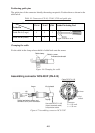
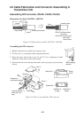
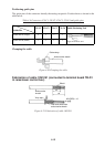
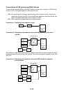
Fabrication of cable 10S1259 (connected to terminal board TB-B1)
Armor
250
45 5
3.5sq
x 3
1.25sq
x 2
M4 (YEL) x 3
M4 (RED) x
2
Figure 4-17 Fabrication of cable 10S1259