


4. INSTALLATION
40
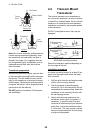
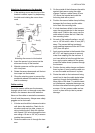
3. Using a 4 mm, #23, or 9/64" bit, drill three
holes 22 mm (7/8") deep at the locations
indicated. To prevent drilling too deeply,
wrap masking tape around the bit 22 mm
(7/8") from the point.
Fiberglass hull: Minimize surface crack-
ing by chamfering the gelcoat. If a cham-
fer bit or countersink bit is not available,
start drilling with a 6mm or 1/4" bit to a
depth of 1 mm (1/16").
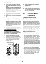
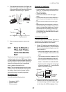
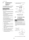
4. If you know your transom angle, the
bracket is designed for a standard 13°
transom angle.
11°-18° angle: No shim is required. Skip
to step 3 in "Adjustments".
Other angles: The shim is required. Skip
to step 2 of "Adjustments".
If you do not know the transom angle,
temporarily attach the bracket and sensor
to the transom to determine if the plastic
shim is needed.
5. Using the three #10 x 1-1/4" self-tapping
screws, temporarily screw the bracket to
the hull. DO NOT tighten the screws com-
pletely at this time. Follow the step 1-4 in
"Attaching the sensor to the bracket", be-
fore proceeding with "Adjusting".
Adjustments
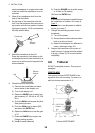
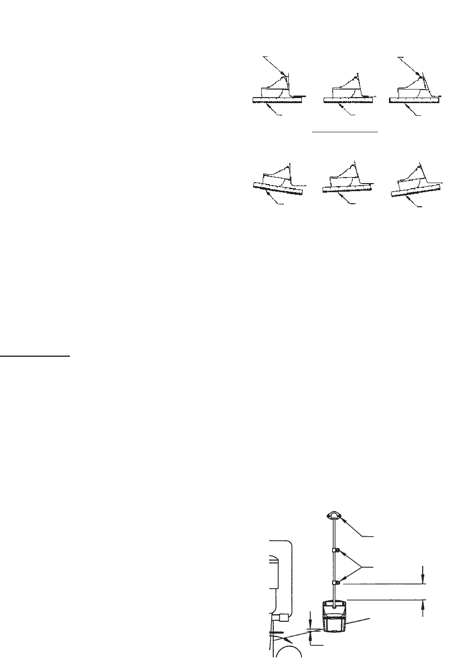
1. Using a straight edge, sight the underside
of the sensor relative to the underside of
the hull. The stern of the sensor should be
1-3 mm (1/16-1/8") below the bow of the
sensor or parallel to the bottom of the hull.
Note: Do not position the bow of the sen-
sor lower than the stern because aeration
will occur.
2. To adjust the sensor's angle relative to
the hull, use the tapered plastic shim pro-
vided. If the bracket has been temporarily
fastened to the transom, remove it. Key
the shim in place on the back of the brack-
et.
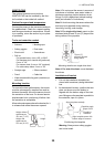
2°-10° transom angle (stepped tran-
som and jet boats): Position the shim
with the tapered end down.
19°-22° transom angle (small alumi-
num and fiberglass boats): Position the
shim with the tapered end up.
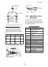
Sensor position and transom angle
3. If the bracket has been temporarily fas-
tened to the transom, remove it. Apply a
marine sealant to the threads of the three
#10 x 1-1/4" self tapping screws to pre-
vent water seeping into the transom.
Screw the bracket to the hull. Do not tight-
en the screws completely at this time.
4. Repeat step 1 to ensure that the angle of
the sensor is correct.
Note: Do not position the sensor farther
into the water than necessary to avoid in-
creasing drag, spray, and water noise
and reducing boat speed.
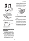
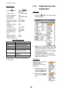
5. Using the vertical adjustment space on
the bracket slots, slide the sensor up or
down to provide a projection of 3 mm (1/
8"). Tighten the screws.
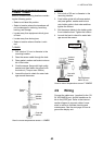
Vertical adjustment and cable routing
2°-10°
transom
angle
11° transom angle
NO SHIM
19°-22°
transom
angle
shim with
taper down
shim with
taper up
YES
YES
YES
parallel parallel
parallel
12°-18° transom angle
NO SHIM
NO NO
YES
angle
reversed
slight
angle
angle too
steep
Cable cover
Cable
clamp
50 mm (2")
Hull projection 3 mm (1/8")