


4. INSTALLATION
44
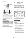
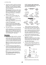
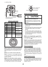
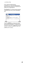
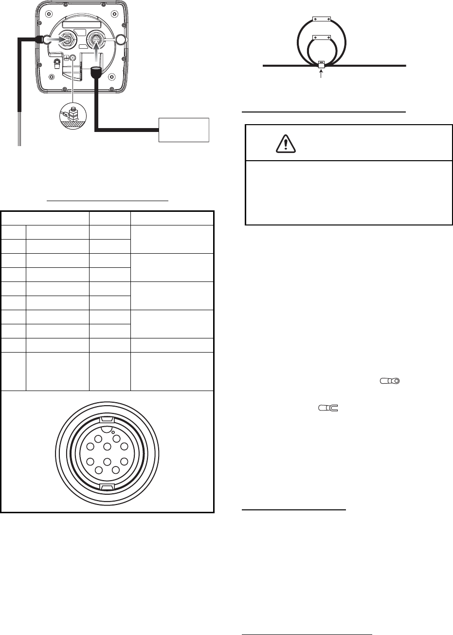
Cable assy. signal names
Note 1: Attach the MJ cable cap (supplied) to
the transducer cable to protect the connector
when the display unit is removed from the
boat.
Note 2: Cut unused cores and tape them.
Note 3: Connector of cable edge breaks eas-
ily. Be careful when connecting or disconnect-
ing the connector.
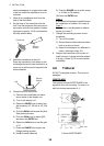
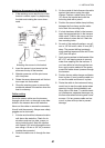
Note 4: The fuse holder contains a spring
which fixes the fuse. To prevent detachment
of the spring, which would cause loss of pow-
er, tie the lines as shown on the next page.
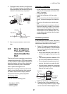
How to ground the display unit
• Use a 1.25 sq wire (local supply) for the
ground wire.
• Make the length of the ground wire as short
as possible and connect it to the boat’s
ground.
• For FRP vessel, attach a steel plate mea-
suring 20 cm by 30 cm on the outside of the
hull to provide a ground point. Connect the
ground wire there.
Note 1: Use a ring-type lug ( ) to make
the connection at the display unit. Do not use
a fork-type lug ( ).
Note 2: For the boat with positive polarity DC
power and the fish finder is grounded to the
hull, external equipment cannot be connected
directly to the fish finder if the signal line of the
equipment is connected to ground.
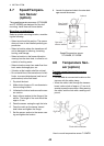
External equipment
The [12-24 VDC/NMEA] port is commonly
used for connection of external equipment
such as a GPS receiver and/or wind indicator.
This port is also used to connect the radio
transmitter for the Tankenmaru system. Refer
to the interconnection diagram to connect ca-
bles.
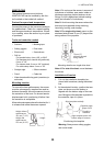
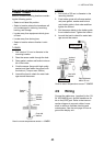
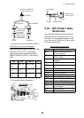
Speed/Temperature sensor
Connect the optional speed/temperature sen-
sor to the XDR port with the optional conver-
sion cable (Type 02S4147) as shown in the
opposite column.
Connector Color Remarks
1 TD-A WHT IEC61162-1/
NMEA0183
2TD-B BLU
3 RD-A YEL IEC61162-1/
NMEA0183
4 RD-B GRN
5 12V-P(+) BRN Power output
(12 VDC)
6 12V-M(-) ORG
7 DC-P-IN (+) RED Power input
12-24 VDC
8 DC-M-IN (-) BLK
9NC –
10 SHIELD – Drain wire (to
GND terminal
on switchboard)
Transducer
cable
Ground
Switchboard, ground terminal,
external equipment
Cable assy.
(KON-004-02M, 2 m)
Transducer
Example:
FCV-627
(option)
1
2
3
4
5
6
7
8
9
10
CAUTION
Be sure to ground the display unit.
An improper ground or no ground can affect
performance and cause interference to other
equipment.
Fuse holder
Power supply lines
(red and black)
Cable tie