


34
4.6 Optional Water
Temperature/Speed
Sensor
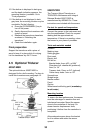
Water temperature/speed sensor
ST-02MSB and ST-02PSB, which are
designed for thru-hull mounting, are
optionally available. Install them as shown
below.
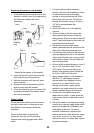
Mounting considerations
Choose a suitable mounting location
considering the following:
•
Choose a place free from vibration.
•
Choose a mid-boat flat position. The
sensor does not have to be installed
perfectly perpendicular. The sensor must
not be damaged in dry-docking
operation.
•
Choose a place apart from equipment
generating heat.
•
Choose a place in the forward direction
viewing from the drain hole, to allow for
circulation of cooling water.
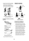
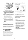
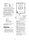
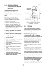
1. Dry-dock the boat.
2. Make a hole of approx. 51 mm diameter
in the mounting location.
3. Unfasten locknut and remove the
sensor section.
4. Apply high-grade sealant to the flange
of the sensor.
5. Pass the sensor casing through the
hole.
6. Face the notch on the sensor toward
boat’s bow and tighten the flange.
7. Set the sensor section to the sensor
casing and tighten the locknut.
8. Launch the boat and check for water
leakage around the sensor.
Locknut
Face "notch"
toward bow.
Flange Nut
Coat with
silicone sealant.
Brim
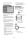
φ
77
51
123
Water temperature/speed sensor
ST-02MSB, ST-02PSB
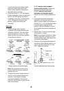
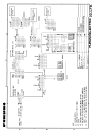
4.7 Wiring
Refer to the interconnection diagram to
connect cables. Leave slack in cables to
facilitate checking and maintenance.
Establishing the ground
The ground wire (1.25sq or more, local
supply) should be as short as possible. The
ground for the signal line is isolated from
the chassis, however the power line is not
insulated. Therefore, to connect external
equipment whose positive polarity is
connected to the ground line, do not
connect the signal line ground to chassis
ground.
The signal line ground is isolated from the
chassis ground, however the power line is
not insulated. Therefore, when connecting
external equipment having positive ground,
do not ground the signal line to the chassis.
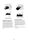
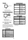
If excessive noise shows on the screen, the
ground may be inadequate. In this case,
attach a steel plate measuring 20 cm by 30
cm on the outside of the hull to provide a
ground point. Connect the ground wire
there. Use a “closed” type lug (
) to
make the connection at the display unit. Do