


190-00906-01 GTX 23 Installation Manual
Rev. C Page 2-1
2 INSTALLATION OVERVIEW
2.1 Introduction
This section provides hardware equipment information for installing the GTX 23 Mode S transponder,
related hardware, and optional accessories. Installation of the GTX 23 should follow the data detailed in
this manual. Cabling is fabricated by the installing agency to fit each particular aircraft. The guidance of
FAA advisory circulars AC 43.13-1B and AC 43.13-2B, where applicable, may be found useful for making
retro-fit installations that comply with FAA regulations.
Refer to Appendix D for rack drawings and dimensions.
2.2 Installation Materials
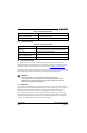
The GTX 23 is available as a single unit under the following part numbers:
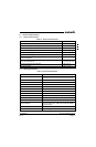
2.2.1 Equipment Available
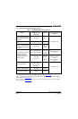
Each of the following accessories is provided separately for the GTX 23 unit. The rack and the remainder
of the accessories are required for installation.
Table 2-1 Installation Materials
Item Catalog Part Number
GTX 23 w/ES, Unit Only, (011-02803-02) 010-01014-02
GTX 23 w/ES and Install Kit, (011-02803-02) 010-01014-03
GTX 23 w/ES, Standard, w/System Rack 010-01014-04
Table 2-2 Equipment Available
Item Garmin Catalog Part Number
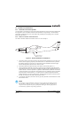
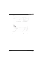
Garmin Transponder Antenna kit** 010-10160-00
Connector Kit, GTX 23 011-01012-01
Back-plate Assembly, GTX 23, BNC* 011-00582-00
Back-plate Assembly, GTX 23, TNC* 011-00582-04
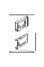
GTX 23 Modular Install Rack 115-00438-00
Or
GTX 23 Stand-Alone Install Rack 115-00629-00
*Only one Backplate Assembly required, installer’s choice of BNC or TNC connector.
**Note: A transponder antenna approved to TSO C66( ) or C74( ) that has been installed to meet the
requirements of this manual may be used with the GTX 23.