


190-00906-01 GTX 23 Installation Manual
Rev. C Page A-1
APPENDIX A CONSTRUCTION AND VALIDATION OF STRUCTURES
A.1 Static Test Loading
This appendix includes information necessary for testing load-carrying capabilities of equipment mounting
structures, such as shelves, mounting plates and mounting brackets, used to mount the GTX 23 remote
mounting racks.
Baggage compartments and cabins or cockpit floors are good mounting platforms providing the floor
attachments meet the strength requirements. If support racks, brackets or shelves need to be fabricated,
consider fabricating and attaching them to the aircraft structure in accordance with the methods outlined in
AC 43.13-2B Chapter 2. After the structure is installed, consider testing it as outlined in AC 43.13-2B
Chapter 1 to verify that it is capable of supporting the required loads.
The GTX 23 installation must be capable of withstanding the Ultimate Load Factors listed in Table A-1 for
at least 3 seconds in each direction specified without damage or permanent deformation. Note that these
required loads differ somewhat from those normally required for equipment installations.
Since the combined weight of the GTX 23 and its equipment mounting rack and connector is 4.3 lbs, the
static loads which must be applied (Load Factor x 4.3 lbs.) will be as follows:
A.2 Determining Static Load Capability
A recommended method of determining the static load capability is as follows:
1. Mark and drill the holes where the GTX 23 equipment rack will be mounted.
2. Install four 8-32 machine screws (MS35206, AN526 or other approved fastener) in the four holes
which will be used to mount the GTX 23 equipment rack using washers, nuts and nutplates to
mount the equipment rack to the mounting surface. Note that some means of locking fastener
must be used, e.g. either lock nuts or steel nuts with lock washers.
3. For testing downward loading, place shot bags or other suitable weights totaling 28.4 pounds
within the footprint outlined by the four screw holes (assuming the mounting surface is horizontal)
or use a calibrated force gauge at the location of the center of gravity when the unit is mounted.
4. Verify there is no damage or permanent deformation of the structure after 3 seconds.
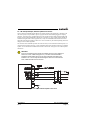
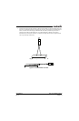
5. Fasten a 36 inch loop of suitable material such as fishing line, braided wire, or other similar
material having a breaking strength of at least 100 lbs., diagonally between two of the screws.
Then fasten another loop diagonally between the other two screws, adjusting the length of the loop
so it exactly matches the first.
6. Hook a calibrated force gauge through both loops and apply a sustained pull for at least 3 seconds
in each of the other three directions (upward, sideward and forward) at the above calculated forces
(i.e. 25.8 lb. upward, 19.4 lb. sideward and 77.4 lb. forward).
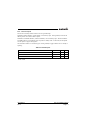
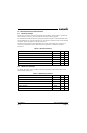
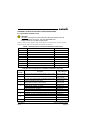
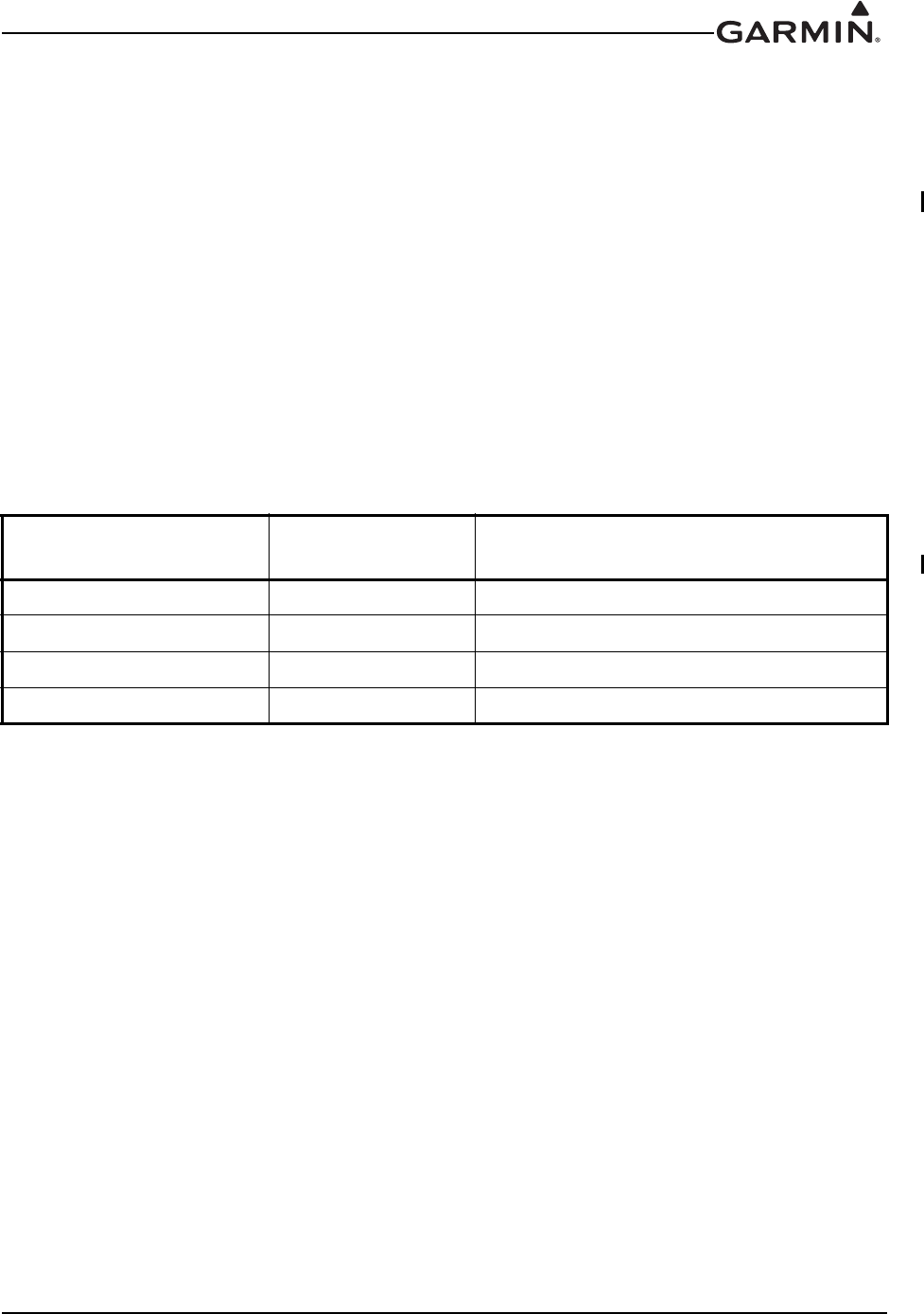
Table A-1 Static Test Load
Direction of Force Load Factor
Static Test Load
(Load Factor x GTX 23 weight)
DOWNWARD 6.6 G (6.6 x 4.3) = 28.4 lbs
UPWARD 6.0 G (6.0 x 4.3) = 25.8 lbs
SIDEWARD 4.5 G (4.5 x 4.3) = 19.4 lbs
FORWARD 18.0 G (18.0 x 4.3) = 77.4 lbs