


190-00906-01 GTX 23 Installation Manual
Rev. C Page 2-5
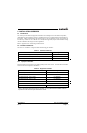
2.4.1 Cable Routing Considerations
After the cable assemblies are made and wiring installed to the rack back plate, route wiring bundle as
appropriate. Use cable ties to secure the cable assemblies and coax to provide strain relief for the cable
assemblies. When routing cables, observe the following precautions:
• All cable routing should be kept as short and as direct as practical.
• Avoid sharp bends to prevent insulation from being breached.
• Avoid routing close to sharp edges to prevent insulation from being breached due to vibration or
handling the cable.
• Avoid routing cables near power sources (e.g., 400 Hz generators, trim motors, etc.) or near power
for fluorescent lighting.
• Avoid routing antenna cables near DME, TCAS, radar altimeter, and ADF antenna cables (allow at
least a 12-inch separation).
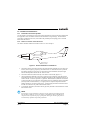
2.5 Cooling Air
Cooling air is generally not required. However, if the unit is located in a confined space or near a source of
heat, cooling air is recommended for maximizing the life of the GTX 23. A 5/8 inch air fitting is provided
on the rear of the backplate for the purpose of admitting cooling air. If a form of forced air cooling is
installed, make certain that rainwater or condensation cannot enter and be sprayed on the equipment.
2.6 GTX 23 Mounting Requirements
The GTX 23 mounting surface must be capable of providing structural support and electrical bond to the
aircraft to minimize radiated EMI and provide protection from High-Intensity Radiation Fields (HIRF).
The GTX 23 can be mounted using either a modular rack or a stand-alone rack. Ensure that the GTX 23
chassis has a ground path to the airframe by having at least one rack mounting screw in contact with the
airframe.
The racks can be installed in a variety of locations, such as the electronics bay, under a seat or on an
avionics shelf behind the rear baggage area. Refer to Figure 2-4 for suggested locations. The racks should
be mounted to a surface known to have sufficient structural integrity to withstand additional inertia forces
imposed by the GTX 23 unit, rack, and connectors (see Section 1.7.1 for weight information). If it is
necessary to build a shelf or bracket to mount the GTX 23 racks, or it is not certain that the chosen location
is of sufficient structural integrity, refer to Appendix A for validation of rack mounting structures and
determining static load capability. Leave sufficient clearance between the GTX 23 and any obstruction.
Consider installing the rack in accordance with AC 43.13-2B Chapter 2 “Communication, Navigation, and
Emergency Locator Transmitter System Installations”.
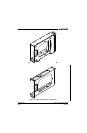
2.6.1 Stand-alone Rack Considerations
Figures 2-2, D-1, and D-2 show the GTX 23 remote-mounted stand-alone rack. Figure D-1 gives the stand-
alone rack dimensions for the GTX 23. The rack can be mounted vertically using four 8-32 pan head
screws (MS35206, AN526 or other approved fastener). It can also be mounted horizontally using four 6-32
100° counter-sunk flathead screws (MS24693, AN507R or other approved fastener). If more water-
resistance is desired, the rack should be installed in the upright vertical orientation only, otherwise, the rack
may be mounted in either vertical or horizontal orientation.
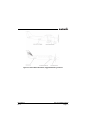
2.6.2 Modular Rack Considerations
Figures 2-3, D-3, and D-4 show the GTX 23 remote-mounted modular rack. Figure D-3 gives the modular
rack dimensions for the GTX 23. The modular rack can be mounted in any orientation and must be secured
to the airframe using a minimum of eight 6-32 100° counter-sunk flathead screws (MS24693, AN507R or
other approved fastener), two per position as indicated in Figure D-4.