


190-00906-01 GTX 23 Installation Manual
Rev. C Page B-8
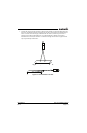
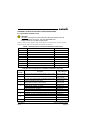
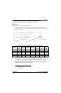
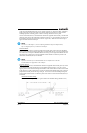
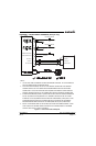
At the end of the shielded cable (Item 4), strip “Quick Term Min” to “Quick Term Max” (Table B-4)
length of the jacket to expose the shield. Next trim the shield so that at most 0.35 inches remains
extending beyond the insulating jacket. Fold this remaining shield back over the jacket.
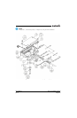
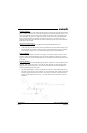
Connect a Flat Braid (Item 6) to the folded back shield of the prepared cable assembly. The flat braid
should go out the front of the termination towards the connector. It is not permitted to exit the rear of
the termination and loop back towards the connector (Figure B-5). Make this connection using an
approved shield termination technique.
NOTE
FAA AC 43.13-1B Chapter 11, Section 8 (Wiring Installation Inspection Requirements)
may be a helpful reference for termination techniques.
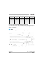
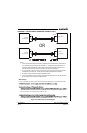
Preferred Method:
Slide a solder sleeve (Item 5) onto the prepared cable assembly (Item 4) and connect the Flat Braid
(Item 6) to the shield using a heat gun approved for use with solder sleeves. It may prove beneficial to
use a solder sleeve with a pre-installed Flat Braid versus having to cut a length of Flat Braid to be used.
The chosen size of solder sleeve must accommodate both the number of conductors present in the
cable and the Flat Braid (Item 6) to be attached.
NOTE
Reference Section B.2 for recommended solder sleeves and flat braid. The same
recommendations are applicable to this technique.
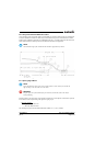
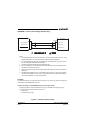
Secondary Method:
Solder a Flat Braid (Item 6) to the folded back shield on the prepared cable assembly (Item 4). Ensure
a solid electrical connection through the use of acceptable soldering practices. Use care to avoid
applying excessive heat that burns through the insulation of the center conductors and shorts the shield
to the signal wire. Slide a minimum of 0.75 inches of Teflon heat shrinkable tubing (Item 5) onto the
prepared wire assembly and shrink using a heat gun. The chosen size of heat shrinkage tubing must
accommodate both the number of conductors present in the cable as well as the Flat Braid (Item 6) to
be attached.
Teflon Heat Shrinkable Tubing:
Reference the following MIL-Spec for general Teflon heat shrinkable tubing (M23053/5-X-Y)
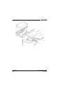
Figure B-5 Method B.1 (Quick Term) for Shield Termination