


190-00906-01 GTX 23 Installation Manual
Rev. C Page 4-5
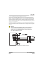
4.3 Serial Data Electrical Characteristics
4.3.1 RS-232 Input/Output
RS-232 input #1 is used to receive pressure altitude control commands. RS-232 output #1 provides unit
status and TIS data. RS-232 #1 input and output are also used for software upgrades.
For installations that enable ADS-B, RS-232 input #2 should be connected to a GNS 400W/500W-series
WAAS enabled unit or a GTN 6XX/7XX series unit. This connection provides the GTX 23 with GPS data
for ADS-B. The RS-232 output #2 is unused on the GTX 23.
The RS-232 outputs conform to EIA Standard RS-232C with an output voltage swing of at least ±5 V
when driving a standard RS-232 load. Refer to figures in Appendix C for the RS-232 serial data
interconnect.
4.3.2 ARINC 429 Input/Output
The ARINC 429 outputs conform to ARINC 429 electrical specifications when loaded with up to five
standard ARINC 429 receivers.
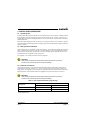
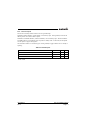
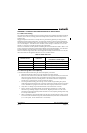
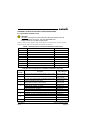
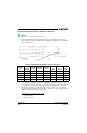
Table 4-5 RS-232 Input/Output
Pin Name Connector Pin I/O
RS-232 OUT 1 P2301 23 Out
RS-232 GROUND 1 P2301 43 --
RS-232 IN 1 P2301 22 In
RS-232 OUT 2 P2301 25 Out
RS-232 IN 2 P2301 24 In
RS-232 GROUND 2 P2301 50 --
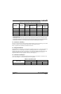
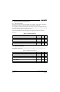
Table 4-6 ARINC 429 Input/Output
Pin Name Connector Pin I/O
ARINC 429 OUT 1A P2301 37 Out
ARINC 429 OUT 1B P2301 34 Out
ARINC 429 OUT 2A P2301 30 Out
ARINC 429 OUT 2B P2301 28 Out
SIGNAL GROUND P2301 51 --
SIGNAL GROUND P2301 58 --