


190-00906-01 GTX 23 Installation Manual
Rev. C Page 4-6
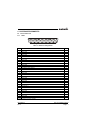
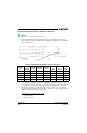
4.4 RS-232 Input/Output, Software Update Connections
GTX 23 software is updated using the RS-232 #1 interface. When wiring the RS-232 #1 interface to the
rest of the system, it may be useful to splice in a pigtail connector that could be plugged into a laptop
computer. Also when wiring, consider that the GTX 23 must be turned on (during software update) and
the other avionic equipment attached to the RS-232 #1 interface (e.g. GSU or GDU) must be turned off.
Instead of turning the other avionic equipment off, a relay can be installed that disconnects the avionic
equipment and connects the laptop to the GTX 23. This connector may be useful for updating software to
comply with new ADS-B regulation.
The connector can be mounted anywhere convenient for access, such as under the instrument panel, on a
remote avionics shelf next to the unit, or in the instrument panel itself. Label the connector “For Software
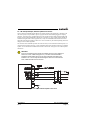
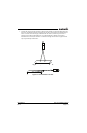
Update”. Do not include the Test Mode Select switch in the aircraft. See Figure 4-2 for software update
connections.
CAUTION
If the unit is removed from the aircraft and operated, always connect J2302 to an
antenna or a 50 , 5-Watt load (Figure 4-2). The GTX 23 transmits Mode S
acquisition squitter replies about once per second whether interrogations are
received or not. The unit may become damaged if J2302 is not connected to a
50 , 5-Watt load when the unit transmits.
Figure 4-2. GTX 23 Software Update Connections
GTX 23
50Ω
5 WATT