


190-00906-01 GTX 23 Installation Manual
Rev. C Page B-10
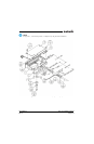
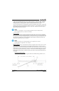
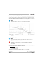
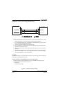
B.6 Daisy Chain between Methods A and B
In rare situations where more braids need to be terminated for a connector than three per ring terminal and
a mixture of Methods A and B have been used, it is allowable to daisy chain a maximum of two shields
together from a Method A termination to a Method B (Figure B-7). All other restrictions and instructions
for the shield termination technique set forth for Method A and B are still applicable.
NOTE
The maximum length of the combined braids should be approximately 4 inches.
Figure B-7 Daisy Chain between Methods A and B
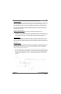
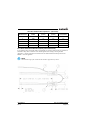
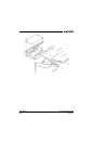
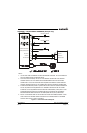
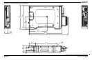
B.7 Splicing Signal Wires
NOTE
Figure B-8 illustrates that a splice must be made within a 3 inch window from outside the
edge of clamp to the end of the 3 inch max mark.
WARNING
Keep the splice out of the backshell for pin extraction, and outside of the strain relief to
avoid preloading.
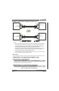
Figure B-8 shows a two wire splice, but a maximum of three wires can be spliced. If a third wire is spliced,
it is located out front of splice along with signal wire going to pin.
Splice part numbers:
• Raychem D-436-36/37/38
• MIL Spec MIL-S-81824/1
This technique may be used with shield termination methods: A.1, A.2, B.1, and B.2.