


Installation
14 3A0869J
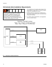
Fluid Supply
Requirements
ProMix 2KE models are available to operate air spray or
air-assisted systems with a capacity of up to 3800
cc/min.
• Fluid supply pressure tanks, feed pumps, or circu-
lating systems can be used.
• Materials can be transferred from their original con-
tainers or from a central paint recirculating line.
• See manual 313599 for Coriolis meter installation
and operation instructions.
NOTE: The Coriolis meter can be used only on non-IS
systems 24F080-24F083. When installed on these sys-
tems, the meter’s hazardous location intrinsically safe
status is voided.
• If you are using dynamic dosing, see Fluid Connec-
tions, this page. See also Set Up the Fluid Mani-
fold for Dynamic Dosing, page 16.
NOTE: The fluid supply must be free of pressure spikes,
which are commonly caused by pump stroke change-
over. If necessary, install pressure regulators or a surge
tank on the ProMix 2KE fluid inlets to reduce pulsation.
Contact your Graco distributor for additional information.
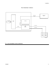
Fluid Connections
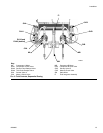
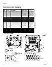
1. See FIG. 6. Connect the solvent supply line to the
1/4 npt(f) solvent valve inlets (SVA and SVB).
2. Connect the component A supply line(s).
• Single color system: connect component supply
line to the component A1 dose valve inlet (DVA1).
• Multiple color system: connect supply lines to the
component A2 and A3 dose valve inlets (DVA2,
DVA3). See F
IG. 6.
NOTE: Solvent supplied by a single source can cause
cross contamination and damage to the system. Install
check valves or use separate solvent sources.
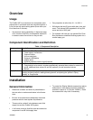
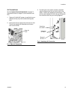
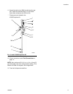
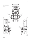
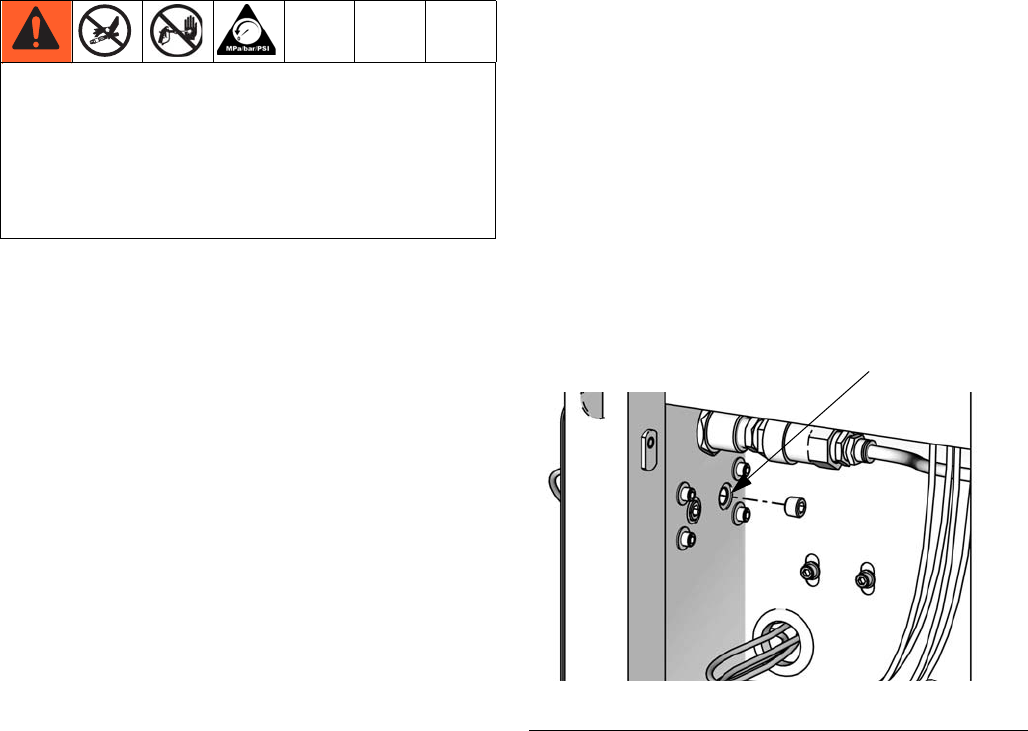
NOTE: Paint Recirculating System Only
• If you are recirculating paint, use the standard inlet
on Dose Valve A1 (A2, A3) or Dose Valve B.
Remove the plug directly opposite it on the dose
valve for the recirculation outlet. The second port is
on the back of the valve and must be reached from
inside the control box.
• Another option is to use a tee fitting to
recirculate.
NOTE: Verify that all unused fluid ports on the color
change valve stack are plugged before operation. An
open port will leak fluid.
3. Connect the component B line to the component B
dose valve inlet (DVB).
NOTE: The component A and B fluid meter inlets have
fluid check valves to prevent backflow from fluid supply
pressure fluctuations. Backflow can cause ratio inaccu-
racies.
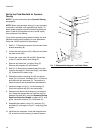
4. Connect the gun fluid supply line between the static
mixer (SM) outlet and the gun fluid inlet.
• Do not exceed the pressure rating of the lowest
rated component. See the identification label.
• To reduce the risk of injury, including fluid
injection, you must install a shutoff valve between
each fluid supply line and the mix manifold. Use
the valves to shut off fluid during maintenance
and service.
FIG. 5. Paint Recirculation Port
Second port
ti16338a