


Dosing Options
3A0869J 53
Dynamic Dosing
Overview
Dynamic Dosing provides on-demand proportioning,
eliminating the need for an integrator and therefore min-
imizing undesired material contact. This feature is espe-
cially useful with shear-sensitive and waterborne
materials.
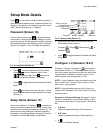
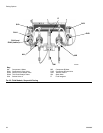
A restrictor injects component B into a continuous
stream of component A. The software controls the dura-
tion and frequency of each injection. See F
IG. 55 for a
schematic diagram of the process.
Dynamic Dosing System Parameters
The following parameters affect dynamic dosing perfor-
mance:
• Component A Flow: Ensure that the supply pump is
sized to provide sufficient and uninterrupted flow.
Note that component A provides majority of system
flow at higher mix ratios.
• Component B Flow: Ensure that the supply pump is
sized to provide sufficient and uninterrupted flow.
• Component A Pressure: Ensure precise pressure
regulation. It is recommended that the component A
pressure be 5-15% lower than the component B
pressure.
• Component B Pressure: Ensure precise pressure
regulation. It is recommended that the component B
pressure be 5-15% higher than the component A
pressure.
NOTE: When using dynamic dosing it is very important
to maintain a constant, well-regulated fluid supply. To
obtain proper pressure control and minimize pump pul-
sation, install a fluid regulator on the A and B supply
lines upstream of the meters. In systems with color
change, install the regulator downstream of the
color/catalyst valve stack.
Select a Component B Restrictor Size
See Set Up the Fluid Manifold for Dynamic Dosing,
page 16. Use the charts on pages 66 to 70 to select an
appropriate restrictor size based on the desired flow and
mix ratio.
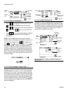
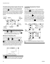
Select Dynamic Dosing
1. On the Display Module press to access Setup
Home (Screen 17). Select to display Configure
1 (Screen 18).
2. Select A B from the dosing type drop down menu.
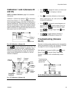
Balancing A/B Pressure
If component B pressure is too high, it will push the com-
ponent A stream aside during B injection. The valve will
not open long enough, causing a Ratio High error.
If component B pressure is too low, it will not be injected
in sufficient volume. The valve will stay open too long,
causing a Ratio Low error.
Selecting the correct component B restrictor size and
balancing the A/B pressures will keep the system in the
proper pressure range, resulting in a consistent mix
ratio.
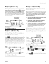
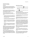
F
IG. 53 shows the A to B pressure balance, read at the
proportioner inlet. It is recommended that the compo-
nent B pressure be 5-15% higher than the component A
pressure to keep the system in the control range, hold
the proper mix ratio, and obtain properly mixed material.
If pressures are not balanced (“B Pressure Too High” or
“B Pressure Too Low”), it may not be possible to hold
the desired mix ratio. The system will generate an off
ratio alarm and stop operation.
NOTE: In multi-flow rate systems, it is recommended
that you set up the system to run properly at the highest
flow rate, to ensure adequate fluid supply across the
flow rate range.
In dynamic dosing, component A dose valve is con-
stantly on. Component B dose valve will cycle on and
off; one cycle every 0.5 – 1.0 seconds indicates proper
balance.
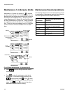
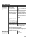
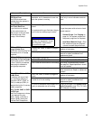
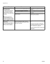
Monitor system performance by watching the Display
Module for warning messages which provide informa-
tion on system performance, and adjust pressures
accordingly. See Table 5 on page 57.